
Types of Antennas on Telecom Towers
Telecom towers utilize sector panels, antennas, and RF microwave dishes to improve overall skills and technical telecom management
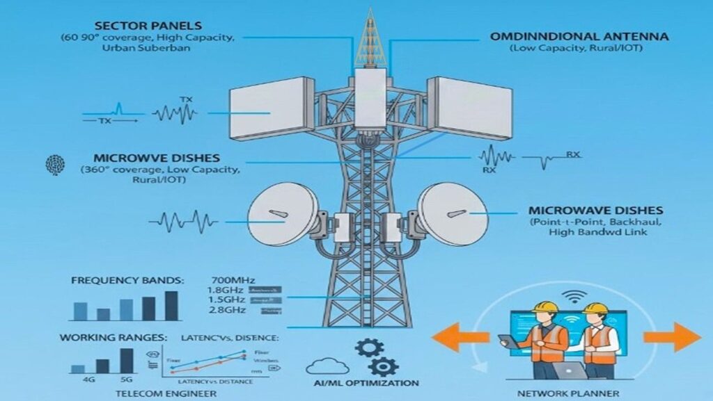
Mobile towers utilize sector panels, omni antennas, and microwave dishes designed for specific frequencies, Working ,ranges, and user densities. Telecom engineers and network planners will find this information useful for understanding their installation and key concepts.
1. Quick Comparison Table
| Antenna Type | Technology | Generation | Coverage Pattern | Primary Purpose |
|---|---|---|---|---|
| Sector Antenna | Patch Array | 2G, 3G, 4G, 5G | Directional (60°–120°) | Main mobile coverage & user access |
| MW (Microwave) Dish | Aperture / Parabolic | Backhaul | Point-to-Point (Narrow) | Inter-site data transmission (Backhaul) |
| AAU (Active Antenna Unit) | Active Massive MIMO | 5G (NR) | Dynamic Beamforming | High capacity, low latency, 5G efficiency |
| Omni-directional | Monopole / Dipole | 2G, 4G, IoT | 360° (Donut shape) | Small cells, rural areas, repeaters |
| GPS / GNSS Antenna | Patch | Synchronization | Skyward | Network timing and site synchronization |
| Yagi-Uda Antenna | Parasitic Array | 2G, 3G, 4G | Highly Directional | Signal boosting in weak or remote areas |

2. Detailed Breakdown & Working Principles
01 Sector Antenna (The Workhorse)
- Design: Typically long, vertical rectangular panels. Inside, they contain a “Patch Array” (multiple small antenna elements) to control the vertical and horizontal beamwidth.
- Working Principle: It uses Constructive Interference. By arranging multiple radiating elements in a vertical line, the antenna “flattens” the signal into a fan shape, focusing energy horizontally toward the users.
- Real-World Example: A standard urban cell site. If you see three panels facing three different directions, each is a sector antenna covering a specific neighborhood.
- Polarization: Most use Cross-Polarization (+45° / -45°) to reduce interference and enhance signal diversity.
- Key Fact: They use Electrical Tilt (RET – Remote Electrical Tilt) which allows engineers to adjust the coverage area from a computer without climbing the tower.
02 Microwave (MW) Dish (The Data Bridge)
- Design: Round, drum-like dishes (often covered with a white plastic “radome”).
- Working Principle: It works like a Flashlight. The parabolic shape reflects all radio energy into a single, high-intensity narrow beam.
- Real-World Example: Connecting a remote mountain-top tower to a city tower where fiber optic cables cannot reach.
- Alignment: Requires sub-degree precision in alignment (Azimuth and Elevation) to minimize RSL (Received Signal Level) loss.
- Requirements: They require Line of Sight (LOS). Even a tree growing into the path can disrupt the connection.
- Key Fact: They operate at very high frequencies (6GHz to 80GHz+), allowing for fiber-like speeds over the air.
03 AAU / Integrated Antenna (The 5G Powerhouse)
- Design: Thick, heavy panels that combine the RRU (Remote Radio Unit) and the antenna into one box.
- Working Principle: Massive MIMO & Digital Beamforming. It uses an array of up to 192 tiny antenna elements. By shifting the “phase” of the signal at each element, it can steer the beam electronically in 3D space.
- Real-World Example: A crowded football stadium. The AAU can create a dedicated “beam” for a specific group of users in one section of the stands to maintain high speeds.
- Energy Efficiency: Integrated design removes the need for long coaxial feeders, reducing Insertion Loss significantly.
- Feature: 3D Beamforming. Instead of a static “floodlight” of signal, the AAU creates a “spotlight” that follows individual users as they move.
04 Omni-directional Antenna (360° Reach)
- Design: Thin, rod-like cylinders.
- Working Principle: It radiates energy equally in all horizontal directions. Imagine a Donut shape—the signal goes out all around but not much goes straight up or down.
- Real-World Example: Small cell poles in a shopping mall or a repeater in a rural village with very few users.
- Mounting: Often placed on the very top of a tower or on the ends of arms to avoid “shadowing” from the tower structure.
- Key Fact: While they cover 360°, they have lower “gain” (range) because the energy is spread thin in all directions rather than focused.
05 GPS / GNSS Antenna (The Clock)
- Design: Small, “puck-like” or “mushroom” shaped antennas usually mounted on the top or a side arm.
- Working Principle: High-sensitivity Satellite Reception. It listens for time-stamped signals from multiple satellites (GPS, GLONASS, Galileo) to calculate an exact time reference.
- Clear View Requirement: Must have a 180-degree unobstructed view of the sky to lock onto the required number of satellites (minimum 4).
- Importance: Without microsecond-level synchronization, 4G and 5G handovers would fail, and interference would crash the network.
3. Field Implementation: Hardware & Software
Hardware Tools (The “Kit”)
- Site Master (Anritsu/Viavi): For testing VSWR, Return Loss, and Distance-to-Fault (DTF).
- PIM Tester: To detect Passive Intermodulation caused by loose connectors or rusty bolts.
- Laser Rangefinder & Inclinometer: To measure height and exact Mechanical Tilt.
- Sunsight/3Z Alignment Tool: Professional GPS-based alignment for precision azimuth/tilt.
- Optical Fiber Tester: Essential for OTDR, ILM, and fiber probe inspection.
Software & Ecosystems
- RF Planning: Atoll, Forsk, or Asset to simulate coverage, interference, and capacity.
- MW Link Design: Pathloss 5 or IQLink for calculating Microwave reliability (Fresnel Zone).
- Configuration: M2000 (Huawei), ENM (Ericsson), or NetAct (Nokia) for scripts and alarms.
- GIS & Site Audit: Google Earth Pro, ArcGIS, and custom mobile audit apps for site photos/data.
4. Essential Concepts for Field Engineers
RF Propagation & Fresnel Zone:
Understanding frequency behavior and keeping the “ellipsoid” path of Microwave links clear of obstacles.
VSWR, Return Loss & PIM:
Troubleshooting power reflection and noise caused by bad connectors or environmental metal interference.
Azimuth, Tilt (MT/ET) & Height:
The three pillars of optimization. Precision alignment ensures the “Main Lobe” of the signal hits the target area.
Earthing & Surge Protection:
Ensuring all antennas are grounded to the tower’s lightning protection system to prevent equipment burnout.
Fiber-to-the-Antenna (FTTA):
Technical SFP modules, digital-to-optical conversion, and cleaning fiber faces to avoid signal dropouts.
5. Emerging Trends: 5G-Advanced and 6G
Small Cells & IAB
Integrated Access and Backhaul. Using 5G signal as both user coverage and the backhaul itself.
RIS (Smart Surfaces)
Reconfigurable Intelligent Surfaces that reflect and steer signals around building corners.
Terahertz & mmWave
Ultra-high frequencies for 6G, requiring extremely dense antenna arrays and AI steering.