
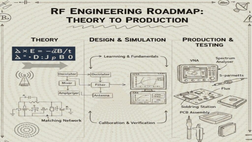
Model of RF Engineering Roadmap
From Fundamentals to Production: A comprehensive journey for the proficient RF Engineer.
🔹 Phase 1: Fundamentals of RF Engineering
The bedrock of all high-frequency design. Without these concepts, simulation and measurement will lack context.
F101 – Fundamentals of RF Circuits
- Physical Principles: Understanding Frequency (f), Wavelength (λ), and Bandwidth (BW). Velocity of propagation in different media (v = c / √εᵣ).
- Impedance Matching: The Smith Chart (admittance/impedance circles), VSWR, Reflection Coefficient (Γ), Return Loss (RL), and Maximum Power Transfer theorem.
- Transmission Lines: Coaxial, Microstrip, Stripline, Coplanar Waveguide (CPW), and Waveguides. Characteristic impedance (Z₀) and propagation constants.
- S-Parameters: Understanding S₁₁ (Input Return Loss), S₂₁ (Gain/Insertion Loss), S₁₂ (Isolation), and S₂₂ (Output Return Loss) in multi-port networks.
F102 – RF Components
- Parasitics: Self-Resonant Frequency (SRF), Equivalent Series Resistance (ESR), and Quality Factor (Q) for resistors, capacitors, and inductors at GHz frequencies.
- Passives: Design and application of Filters (Butterworth, Chebyshev, Elliptic), Bi-directional Couplers, Power Dividers (Wilkinson), Circulators, and Isolators.
- Actives:
- Amplifiers: Low Noise Amplifiers (LNA), Power Amplifiers (PA Classes A, AB, C, D, E, F).
- Frequency Conversion: Mixers (Single/Double Balanced), Local Oscillators (LO), and Frequency Synthesizers (PLL/VCO).
F103 – RF Systems (Analog & Digital)
- Architectures: Superheterodyne, Direct Conversion (Zero-IF), Low-IF, and Software Defined Radio (SDR) front-ends.
- Modulation:
- Analog: AM, FM, PM.
- Digital: BPSK, QPSK, n-QAM, OFDM, and Spread Spectrum (FHSS/DSSS).
- System Budgeting: Calculating Cascaded Noise Figure (NFₜₒₜₐₗ), Cascaded Gain, Linearity (P1dB, IIP3, OIP3), Sensitivity, and Dynamic Range (SFDR).
🔹 Phase 2: RF Simulations
Translating theory into virtual models to predict real-world performance.
S101 – Fundamentals of RF Simulations
- Simulation Types: Circuit (Linear/Non-linear: SPICE, Harmonic Balance, Envelope) and EM (Full-wave: FEM, MoM, FDTD).
- Setup: Defining Boundary conditions (PEC, Radiation/Absorbing), Port types (Wave, Lumped, Internal), and Mesh refinement/convergence.
S102 – RF Structure Simulators (Ansys HFSS / CST Studio / FEKO)
- Antenna Design: Patch antennas, Monopoles, Dipoles, Horns, and Phased Arrays.
- Analysis: Far-field Radiation patterns, Directivity, Gain, Efficiency, Axial Ratio, and Co-polarization vs. Cross-polarization.
- Structure Analysis: Modeling connectors (SMA/SMP), transitions (Microstrip to Waveguide), and cavity resonators.
S103 – RF Circuit/System Simulators (Keysight ADS / AWR / SystemVue)
- Circuit Optimization: Monte Carlo analysis, Yield analysis, and Tuning matching networks/bias tees.
- Non-linear Analysis: Intermodulation Distortion (IMD) products, X-parameters, and Load-Pull simulation for PA design.
- System Validation: Analyzing Link Budgets, Bit Error Rate (BER), Error Vector Magnitude (EVM), and Spectral Mask compliance.
🔹 Phase 3: RF Design Implementation
Moving from idealized simulations to physical hardware constraints.
D101 – Fundamentals of RF PCB Design
- Substrates: Selecting materials (Rogers, Megtron, FR-4), understanding Dissipation Factor (tan δ), and Dielectric Constant (εᵣ) stability.
- Layout Techniques: Controlled impedance traces, ground stitching (vias), microstrip vs. stripline isolation, and minimizing crosstalk.
- Thermal Management: Thermal vias, heat sinks for PAs, and material glass transition temperature (Tᵍ).
D102 – Fundamentals of EMI / EMC & SI/PI
- Integrity: Signal Integrity (reflections, eye diagrams) and Power Integrity (decoupling networks, PDN impedance).
- EMC Design: Faraday cages, shielding cans, Ferrite beads, and differential signaling.
- Compliance Standards: Preparing for Regulatory testing (FCC Part 15, CE RED, ETSI, CISPR).
🔹 Phase 4: RF Measurement and Characterization
Verifying that the hardware matches the design requirements using bench equipment.
M101 – Signal Generators
- CW & Sweep: Producing stable sine waves and frequency sweeps.
- Vector Signal Generators (VSG): Generating complex IQ modulated signals (5G NR, LTE, Wi-Fi 6/7) with fading and AWGN profiles.
M102 – Vector Network Analyzer (VNA)
- Calibration: TRL, SOLT, and Electronic Calibration (ECal) modules.
- Advanced Measurements: Time-domain gating, Group delay, Phase linearity, and Multi-port analysis.
M103 – Spectrum & Signal Analyzer (SA/VSA)
- Frequency Domain: Occupied Bandwidth (OBW), ACPR, SFDR, and Phase Noise (dBc/Hz).
- Vector Analysis: EVM, Constellation diagrams, I/Q Offset, and Symbol timing error.
M104 – Time Domain & Power Meters
- Oscilloscopes: Real-time vs. Sampling scopes for High-speed Jitter and Eye Diagram analysis.
- Power Meters: Peak and Average power sensors for calibrated measurements of high-frequency pulses.
🔹 Phase 5: RF Manufacturing and Production
The final stage: ensuring quality, repeatability, and reliability at scale.
P101 – RF Troubleshooting & Failure Analysis
- Debug: Signal tracing using RF probes, thermal imaging for hotspots, and TDR for cable/trace breaks.
- RCA: Root Cause Analysis of field returns (ESD damage, Dielectric breakdown, cold solder joints).
P102 – Test Fixture & ATE Design
- Mechanical: Pogo-pin fixtures, RF shields, and Repeatability/Reproducibility (Gage R&R) studies.
- De-embedding: Software algorithms to remove the loss and phase shift of the test fixture.
P103 – Automated Testing (ATE) & Quality
- Automation: Controlling instruments via SCPI commands using Python (PyVISA), LabVIEW, or C#.
- Production Metrics: Optimizing Test Time, Statistical Process Control (SPC), Yield Improvement, and Reliability testing (HALT/HASS).
- Expert Oversight: The engineer ensures that production lines maintain high standards of spectral purity and signal integrity through continuous monitoring.
- Process Refinement: One analyzes large-scale data sets to identify manufacturing drift, ensuring that every unit meets stringent performance criteria.
- Strategic Optimization: A specialized lead integrates hardware-in-the-loop (HIL) testing to bridge the gap between initial prototyping and final assembly validation.