
Global Inductive Principles
Types, Function, and Applications in Modern Electronics. The fundamental property of electrical inertia and magnetic energy storage.
Standard Inductor Symbol & Circuit
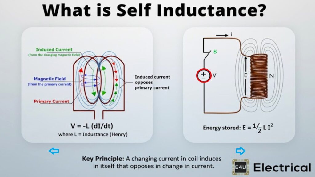
The Faraday-Lenz Law
Voltage is generated when the magnetic flux linkage Φ changes over time.
The negative sign indicates opposition (Lenz’s Law)
Core Principles of Electromagnetism
1. Magnetic Field Creation
When Electric Current flows through a conductor, it generates a circular magnetic field. Coiling the wire concentrates these into a powerful, unified Magnetic Flux.
2. Faraday’s Induction
If current changes, the magnetic field expands or collapses. This moving field induces an Electromotive Force (Voltage). No change = No induced voltage.
3. Lenz’s Law (Inertia)
Induced voltage opposes the change that created it. It acts as Electrical Inertia, pushing back when you try to start or stop flow.
The Flywheel Analogy
An inductor acts like a heavy flywheel: it resists changes in current speed. Energy is required to create the magnetic field, and once established, the inductor resists any interruption, generating a high-voltage spark when broken.
Comprehensive Inductor Classification
← Swipe table horizontally to see all specifications →
Magnetism and Advanced Physics
Flux Density (B)
Measures the “concentration” of magnetic lines. The more dense the flux, the higher the inductive potential.
Permeability (μ)
Magnetic “conductivity.” Ferrite or Iron cores invite fields thousands of times more easily than air.
- Air: μr ≈ 1
- Iron: μr ≈ 5,000
- Permalloy: μr ≈ 100k+
Right-Hand Rule
Wrap fingers with current; thumb points to Magnetic North.
North Pole = Flux Exit Point
Industrial & Real-World Utility

Fig 1.0: Magnetic Field Dynamics Visualized
🔌 Power Smoothing
Chokes block high-frequency noise and “smooth” ripples in DC voltage for stable electronics.
🚗 EV Inverters
Crucial for managing the rapid switching of energy between high-voltage batteries and drive motors.
📡 Radio Tuning
Filters specific frequencies by matching with capacitors in LC resonant circuits.
🛑 Metal Sensing
Security scanners and traffic loops detect the change in inductance when metal enters a field.
Inductive Reactance (XL)
In AC circuits, inductors don’t just “block” current; they resist the rate of change. This frequency-dependent resistance is called Reactance.
High Frequency: XL increases proportionally. Inductors act as “Open Circuits” to electrical noise.
Zero Frequency (DC): XL is zero. Inductors act as a “Short Circuit” or simple wire.
Exemplary Engineering
The EMP
Uses explosive flux compression to crush a magnetic field into a tiny space, causing a massive surge in current that fries electronics for miles.
CERN’s LHC
Superconducting coils at near absolute zero carry 12,000 Amps to bend proton beams at 99.9% the speed of light.
Inductor Synthesis Lab
Physics Logic
Inductance increases with the square of the turns: L ∝ N2. Double the wire, quadruple the storage!
The 90° Phase Shift
Current I lags behind Voltage V by 90°.
The magnetic field buildup creates an inherent time delay.
Practical Design Checklist
Check Saturation Current
Never exceed the rated Isat or the core will lose its permeability, causing a massive current spike.
Self-Resonant Frequency (SRF)
Avoid operating near the SRF; parasitic capacitance makes the inductor act like a capacitor.
DCR Losses
Consider DC Resistance (DCR) for heat management in high-current power stages.
EMI Shielding
Use shielded inductors or toroidal shapes to prevent magnetic noise from interfering with nearby traces.