
Link EVM
0.82%
OptimalTargeting sub-1% for 5G-Adv
Spectrum Efficiency
12.4
bps/HzUsing 1024-QAM Modulation
Throughput
4.2
GbpsPeak mmWave downlink
Latency (RTT)
1.2
msUltra-reliable low-latency (URLLC)
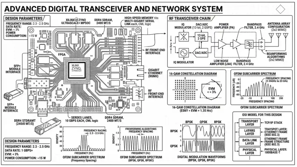
System Block Diagram
Transceiver Front-End Architecture (Heterodyne).👇🏻.Clik to block Diagram
Advanced RF Physics & Implementation Specifics
Phase Noise & LO Stability
At 28GHz (Ka-band), the Phase Noise of the Local Oscillator (LO) becomes the dominant factor in EVM degradation. We utilize a Sub-harmonic Mixer architecture to reduce the requirement on the PLL frequency. By maintaining a Phase Noise floor of -110 dBc/Hz at 100kHz offset, we ensure that the tight constellation points of 1024-QAM do not “rotate” or blur, preventing symbol decision errors at the receiver.
Thermal Steering & GaN Efficiency
The Gallium Nitride (GaN) High Electron Mobility Transistor (HEMT) operates at high power densities. To prevent thermal runaway, AEC implements a Silicon Carbide (SiC) substrate which offers superior thermal conductivity (4.9 W/cm·K) compared to bulk Silicon. This allows for a “Power Added Efficiency” (PAE) boost, ensuring that 45% of DC power is converted to RF, significantly reducing the cooling requirements for base station enclosures.
EMC & Substrate Shielding
Inter-stage isolation is critical in Heterogeneous Integration. We employ Substrate Integrated Waveguides (SIW) to confine EM fields within the PCB layers. By using laser-drilled micro-vias to create Faraday cages around sensitive LNAs, we achieve >60dB of isolation from the high-power PA stages, preventing “self-quieting” where the transmitter’s noise floor masks the incoming weak signals.
AI-Enhanced Signal Recovery
Traditional DSP filters are static, but AEC incorporates a Neural Equalizer. Using a light-weight RNN (Recurrent Neural Network) on the FPGA, the system predicts channel fading patterns in real-time. This dynamic compensation allows for reliable communication even in high-mobility scenarios (e.g., high-speed rail at 300km/h) where Doppler shifts normally collapse standard 5G carrier-tracking loops.
Frequency-Selective Surfaces (FSS)
To mitigate multi-path interference in urban “canyon” environments, AEC designs utilize Metasurface-based FSS. These spatial filters act as programmable mirrors or windows for specific frequency bands. By controlling the surface impedance across the radome, we can reject out-of-band harmonics and interference from adjacent co-located radar systems without adding insertion loss to the primary 28GHz data path.
Real-Time Spectrum Analysis
Monitoring Sub-6GHz and mmWave Bands
Signal Constellation (16-QAM)
GaN PA Schematic (Simplified)
[IN] --||--[R1]--+--[GaN FET]--[OUT]
        C1       |      |
                 +--[L1]--[Vcc]
                 |      |
               [R2]   [C2]
                 |      |
               [GND]  [GND]

// Key Specs:
Vds: 28V
Idq: 200mA
Pout: 43dBm (20W)
Eff: 45.2%
Concept: Load Pull
Circuit is optimized for maximum power transfer by matching complex output impedance.
Working Principle: Digital-to-Wave Transition
Bit Stream Processing
Digital data is mapped into I (In-phase) and Q (Quadrature) components using Grey Coding.
Up-Conversion
The Baseband I/Q signals modulate a carrier frequency via the Mixer, shifting the signal to RF (e.g., 28GHz).
Power Amplification
The weak modulated signal is boosted by the Power Amplifier (PA) to a level sufficient for air-transmission.
Electromagnetic Propagation
The antenna converts electrical currents into Maxwellian EM waves that propagate through space.
Core RF Components
LNA (Low Noise Amp)
NF: 1.2dB | Gain: 20dB
Mixer / Down-converter
Conv. Loss: 6dB
GaN Power Amplifier
Efficiency (PAE): 45%
AEC Design & Testing Lifecycle
Schematic
Impedance matching
Simulation
S-Parameter Analysis
Prototyping
SMD Placement
Verification
Compliance
SDR & Cognitive Radio
Software-Defined Radio allows for extreme flexibility. Instead of fixed hardware filters, we use high-speed FPGA processing to isolate signals, meaning the same hardware can switch from 4G to 5G via a software patch.
Tech Expansion: Beam Management
AEC utilizes Beamforming Refinement where the DSP calculates phase shifts across 64 elements in sub-microseconds, creating narrow, high-gain pencil beams that track users.
3D Heterogeneous Integration
AEC utilizes AiP (Antenna in Package) technology, placing the antenna array directly on the RFIC substrate to eliminate trace-loss at mmWave frequencies where even 1mm of cable causes significant attenuation.
Tech Expansion: Thermal Via Matrix
Incorporating high-aspect-ratio Through-Silicon Vias (TSV) to manage GaN-on-SiC heat density, ensuring thermal gradients do not exceed 10°C across the chip.
EVM Analysis
Testing for signal vector deviation. Vital for high-order QAM reliability.
OTA Chamber
Measuring beamforming accuracy for Antenna-in-Package (AiP) designs.
Digital Twins
Virtual RF environment replication to predict field performance before deployment.
DIBP (Digital Integrated Built-in Probing)
Our advanced testing methodology includes Real-time Self-Characterization. DIBP allows for on-chip monitoring of IIP3 and P1dB points during live operation, enabling autonomous bias adjustments to compensate for hardware aging over a 15-year lifecycle.
Non-Terrestrial Networks (NTN)
Seamless roaming between terrestrial cell towers and LEO satellites.
Terahertz (THz) Communication
Bridging the THz Gap (0.1 – 10 THz) using InP (Indium Phosphide) substrates to enable Tbit/s data rates for holographic telepresence.
Semantic Waveforms
Using AI to transmit Meaning/Context instead of raw bits, significantly increasing the “effective” Shannon capacity by orders of magnitude.
Regulatory Standards
- FCC Part 15 / 27 / 30 Compliance
- 3GPP Release 18 (5G-Advanced)
Dynamic Spectrum Sharing (DSS) Compliance
We strictly adhere to Global Spectrum Allocation rules, implementing sub-millisecond switching logic to allow 4G and 5G coexistence on the same frequency blocks without causing co-channel interference violations.