
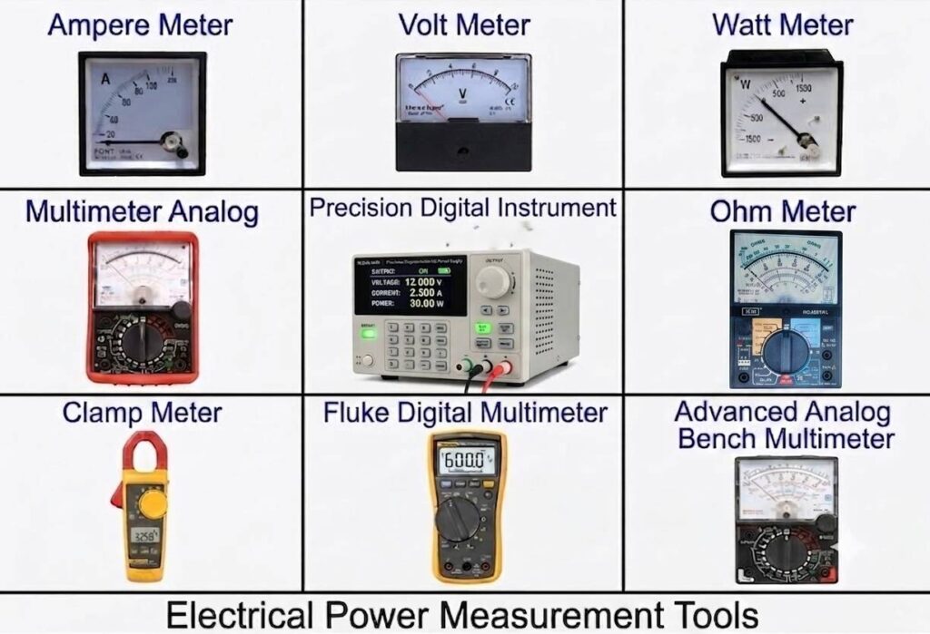
Measuring electrical power with these devices is essential in electrical engineering, maintenance, parameter assessment, and troubleshooting, as they allow us to quantify invisible electrical properties of current, voltage, frequency and power to check device, system and sub-system in operational.
Basic Key Concepts in Electrical Measurement by Instruments:
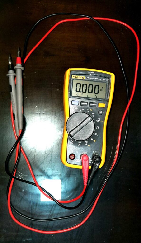
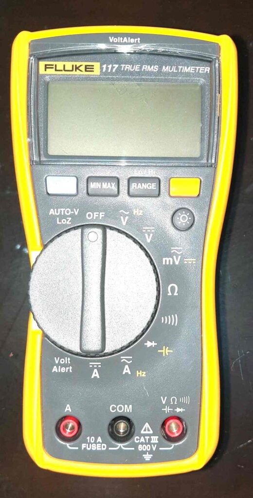
Remark : Before switching on (Power ON)any equipment composing the system, the quality of power input lines must be verified to prevent any damage ,Shortcut on the Hardware ,system or devices or Components.
WARNING
HIGH VOLTAGE, risk of electric shock. Care should be taken.
Basic relationship and follow the Ohm’s Law: V(volts)=IxR,
And other way P (Watt)=VXI,
And F(Hz)=1/T.
How to measure Electrical parameter:
- Voltage (V): The electrical potential difference between two points (measured in Volts) .i.e.= V2-V2
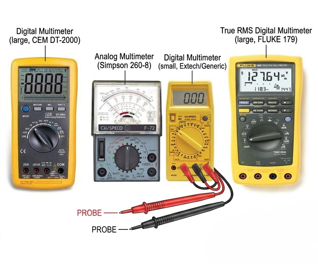
Practical by using Multimeter to measure electrical voltage by Instrument Measurement
Table 1-1. Incoming /Row Power Supply Characteristics by checking instrument.
| Power Supply Characteristics | Single Phase / Three Phase | |
| Applicable standard | NEC IEC UNE | |
| Number of Wires | ||
| Frequency (50Hz / 60HZ) | ||
| Voltage Between Phases | ||
| R Phase (L1) | Colour Code | |
| S Phase (L2) | Colour Code | |
| T Phase (L3) | Colour Code | |
| Neutral (N) | Colour Code | |
| Site Incoming Lines | Number of Incoming Lines (1 or 2) | |
| Capacity (Load KVA) per line |
1.1 INPUT VOLTAGE TESTS
1.1.1 Test Tools
The following tools will be needed to perform all tests:
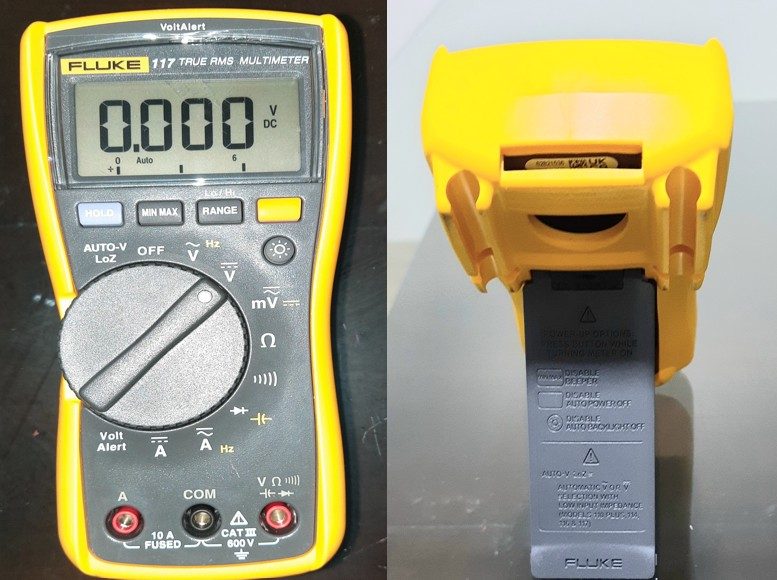
Multimeter.
1.1.2 Test Procedure
Step 1. Note the applicable Normalized Voltage in compliance with contract and Indra specifications. See example below.
Voltage between Phase-Phase (L1-L2, L1-L3, L2-L3): 400V +/- 10%. Voltage between Phase-Neutral (L1-N, L1-N, L2-N): 230V +/- 10%.
Voltage between Neutral-Earth (N-PE): <4V.
Step 2. Having the circuit breakers which correspond to Indra equipment switched off, check at the upper part (upstream) of those breakers
that the voltage between Phases (L1, L2, L3), Neutral and earth match with the specified requirements.
PDB must be fed and MCB switched on, check that all breakers in the upstream of Power system circuit breakers
are switched on. Check that the values match with expected normalized voltage. Do not switch on the breakers
protecting Indra equipment until test is passed.
WARNING
HIGH VOLTAGE, risk of electric shock. Care should be taken
Step 3. Check the right cable section having into account UNE, IEC or NEC specifications for maximum consumption for each line having as maximum current limited by every circuit breaker. Have following table as reference.
Normalized Voltage Approximate:
Voltage between Phase-Phase (L1-L2, L1-L3, L2-L3): 396-420V ~~ 400V
Voltage between Phase-Neutral (L1-N, L1-N, L2-N): 210-240V ~~ 230
Voltage between Neutral-Earth (N-PE) :<5V
Note: Typical Voltage Ranges
| Line | Voltage Range | Common Usage |
| L1 | 110–120 V | Lamps, TVs, computers |
| L2 | 208–240 V | Washing machines, dryers, AC units |
| L3 | ~480 V | Heavy-duty industrial equipment |
Line-to-neutral: ~120 V
Line-to-line: ~230 V (common in commercial buildings)
Industrial setups: ~420 V line-to-line
Line-to-Line Voltage: VLL=Root Square of 3⋅VLN
if V LN=230 V, Then V LL~~400 V.
if VLN =120V, then VLL~~ 208 V.
2.Current (I): The flow rate of electric charge (measured in Amperes)
How to Measure Current with a Multimeter?
Similarly, measurement current by using same instrument
INPUT CURRENT TESTS (Very Difficult to measure)
2.1 Test Procedure
Note: all instrument or Multimeter not capable /Option to measure AC Current so check 1st have or not may me option of DC current so check notation before checking otherwise safety issue .
Step 1. Set a Multimeter rotator dial to Amps(A) Setting mention notation AC or DC (A) of dial and set meter in auto-ranging to avoid burning or fused or damage Multimeter.
Step 2. Rotate probes of Multimeter from the standard “VΩmA” or “Amp” port to the “10A” or “A” port.
Step 3. Before measuring the current and following the instructions provided above, connect the Multimeter in series by placing one probe on the source side of the breaker and the other on the load side. However, please note that this task should only be performed by someone with the appropriate knowledge and experience; do not attempt it at home without the necessary experiences
3.How They Work (Working Principle of instrument)
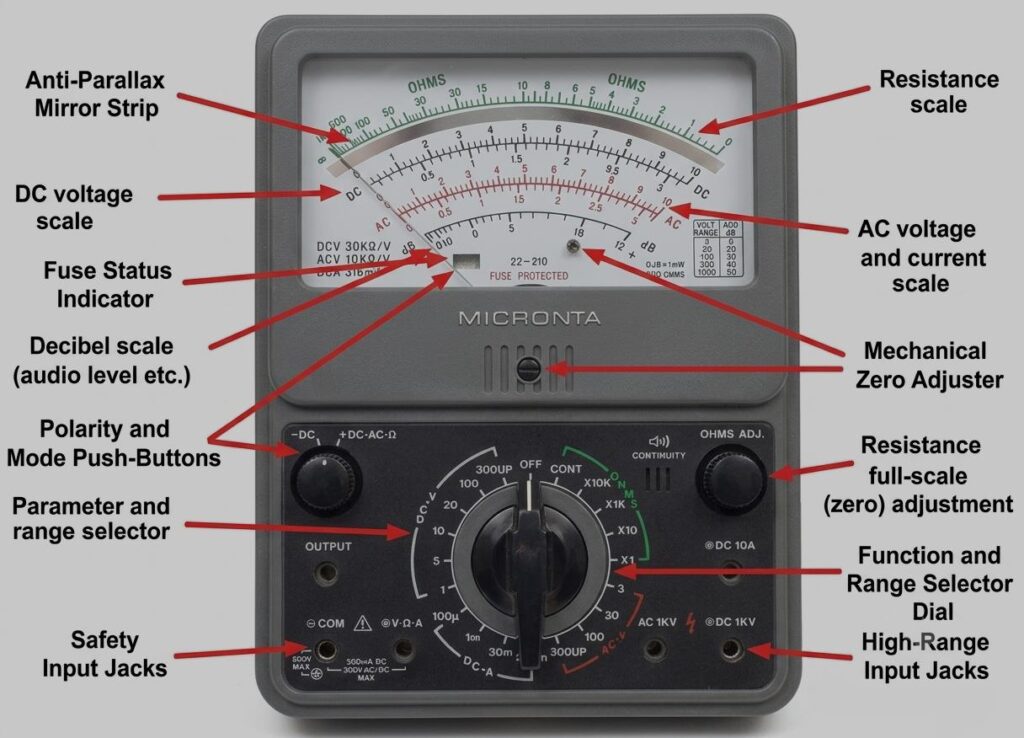
3.1 Analog Meters (Multimeter):
Use a moving coil mechanism (Galvanometer). When current flows through a coil placed in a magnetic field (S-N) as show above pictures, the coil experiences a force that rotates a needle across a calibrated scale to measure electrical parameter value. This instrument required calibration.
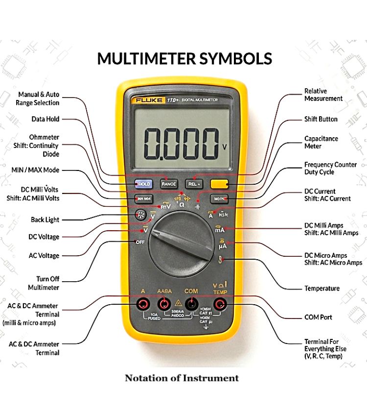
3.2 Digital Multimeter Meters:
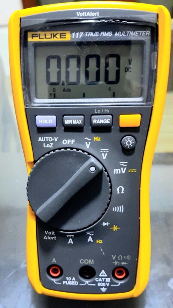
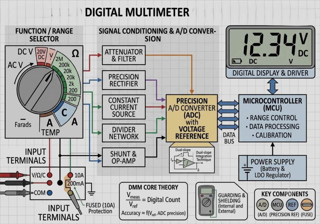
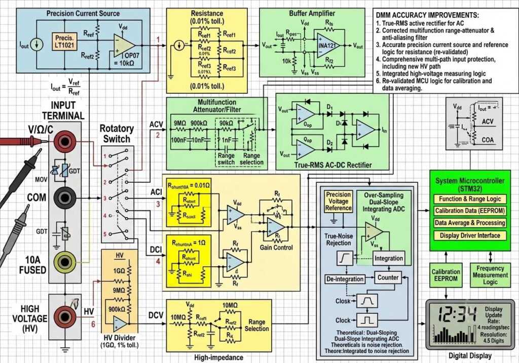
Convert analog signals into digital values using an precision Analog-to-Digital Converter (ADC) with voltage reference and Microcontroller auto range calibrate and perform The result is processed by internal electronics and Digital displayed as a number on an LCD or LED screen as show in fig.
3.3 Clamp Meters:
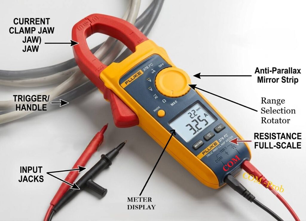
Use a sensor (often a Hall Effect sensor for DC or a Current Transformer for AC) to detect the magnetic field generated to complete paths of MF by the current flowing through a conductor, allowing measurement without breaking the circuit or any probs connection.
3.4 Ohms Meters:
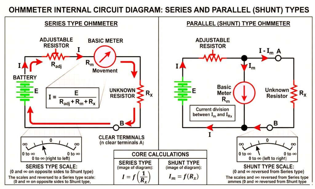
Name its self indicate to measure electrical and electronics Low value resistance also used for continuity test .
in generally 2 types as series and shunt type ohm meter as show fig, in CKT diagram .
3.5 Megger Meters:
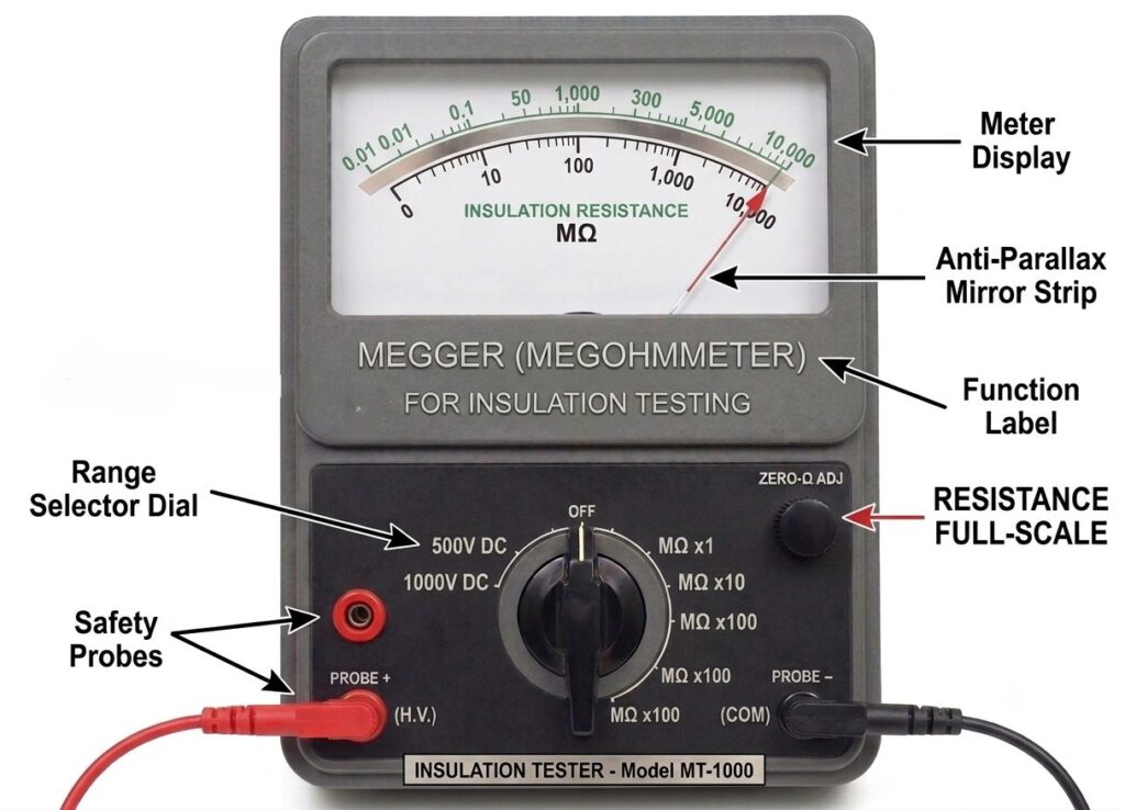
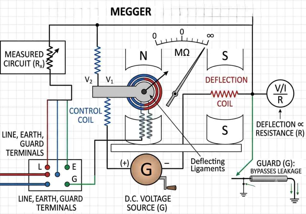
Megger insulation tester Used for insulation resistance and electrical resistance (1kV to 15kV) of electrical cables, transformer, motor to identified faulty to protect system or human life also measure earthing resistance.
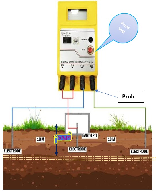
How to measure resistance of earthing: when earthing pits of Gi as to be copper strip to connected one COM prob with strip and another connected to ground and length of cable (distance of cable from earthing pits more than 20m) and angle should be 180 and again measure at angle 90 degree respectively as show fig.
4.Safety and Prevention
Inspect Properly Before Use Instrument: Check probes, cables, and the device body for cracks or short, exposed wires, or damage, then Continuity Test.
Never Touch Live Parts or can’t direct current measure: Use insulated tools, Proper skill and, if possible, work on de-energized circuits.
Correct Setting and calibration: Always ensure the meter is set to the correct function and calibrated (e.g., do not measure current while set to Voltage, as this can destroy the meter and may be shocked).
Personal Protective Equipment (PPE): Use safety glasses, insulated gloves and dress (if) and non-conductive footwear when working with high-energy systems or,PDP, UPS room.
Note: All the instruments or tools used for during the testing, when applicable, shall have a valid Calibration Test Certificate
Why calibration is required in analog Multimeter?
Calibration is a process in which an instrument is compared against a known standard (calibrator) to ensure the accuracy of its measurements. This standard must be traceable to national or international standards. During this process, a known, precise value is applied to the meter, and its reading is compared against that value. If any discrepancy is found, the meter is adjusted, or a correction factor is applied to ensure accurate measurement.