
▸ EMBEDDED SYSTEMS FOR ENHANCING LEARNING MODULE-PART-1
MICROCONTROLLER MASTERY
: REAL-WORLD INDUSTRIAL SKILLS
: REAL-WORLD INDUSTRIAL SKILLS
From zero Stretch to prototype — architecture, coding, PCB design, testing, and troubleshooting in one interactive ‘Information Skills’ module.
ARDUINO
STM32
ESP32
C/C++
MicroPython
PCB DESIGN
DEBUGGING
RTOS
PROTOCOLS
WHAT IS A MICROCONTROLLER?..☝🏻.Scroll.
A microcontroller (MCU) is a compact integrated circuit that contains a processor core, memory (flash + RAM), and programmable I/O peripherals on a single chip. Unlike a microprocessor, it is designed for embedded control applications — running dedicated firmware to interact with the physical world.
8–512
KB FLASH (typical)
1–512
KB RAM
1–1000
MHz CLOCK
2–100
GPIO PINS
μW–mW
POWER RANGE
POPULAR MCU FAMILIES
ARDUINO (AVR/ARM)
ATmega328P, ATtiny, SAMD21. Best for beginners. 8–32-bit. Huge community and library support. 3.3V/5V logic.
STM32 (ARM Cortex)
32-bit ARM Cortex-M0 to M7. Professional grade. HAL/LL drivers. Used in industrial and automotive.
ESP32 / ESP8266
Dual-core 240MHz + Wi-Fi + BLE. Ideal for IoT. 4MB flash. FreeRTOS support. Very cost-effective.
RP2040 (Raspberry Pi)
Dual-core Cortex-M0+. PIO state machines. MicroPython and C SDK. Excellent for custom peripherals.
PIC (Microchip)
8–32 bit. Industry standard. Low power. MPLAB ecosystem. Widely used in automotive and medical.
nRF52 (Nordic)
Bluetooth 5 + BLE SoC. Ultra-low power. Used in wearables, medical devices, smart home.
MCU vs MPU vs SBC
| FEATURE | MICROCONTROLLER | MICROPROCESSOR | SBC (Pi) |
|---|---|---|---|
| OS Required | NO | OPTIONAL | YES |
| Boot Time | Instant (<1ms) | Seconds | 10–60s |
| Power | μW–mW | mW–W | 1–5W |
| Real-Time | EXCELLENT | MODERATE | POOR |
| Cost | $0.10–$5 | $2–$50 | $10–$100 |
| Use Case | Sensors, actuators, control | Signal processing | AI, multimedia, Linux apps |
Learning Path: Start with Arduino Uno (ATmega328P), then move to ESP32 for IoT, then STM32 for professional embedded development. Each step adds complexity and capability.
INTERNAL ARCHITECTURE
VCC 3.3V
GND
RESET
PD0/RX
PD1/TX
PD2/INT0
PD3/INT1
PD5/PWM
PD6/PWM
MICROCONTROLLER
ATmega328P
28-DIP / QFP
16MHz / 32KB / 2KB
PC0/ADC0
PC1/ADC1
PC2/ADC2
PC3/ADC3
PC4/SDA
PC5/SCL
PB0/ICP
PB3/MOSI
PB4/MISO
■ POWER
■ ANALOG
■ PWM/COMM
■ DIGITAL
CORE COMPONENTS
CPU CORE
Arithmetic Logic Unit (ALU), registers (8–32 bit), instruction decoder. Executes one instruction per clock cycle (RISC). Harvard vs Von Neumann architecture.
FLASH MEMORY
Non-volatile program storage. 10,000–100,000 write cycles. In-system programmable (ISP). Stores your compiled firmware (bytes).
SRAM
Volatile working memory. Stack, heap, global variables. Limited (256B–512KB). Overflow causes stack corruption and crashes.
EEPROM
Non-volatile data storage. Survives power cycles. Slower writes (~3ms/byte). Used for calibration data, settings, counters.
TIMERS / PWM
Hardware counters. Generate precise timing, PWM signals (0–100% duty cycle), input capture, output compare interrupts.
ADC
Analog-to-Digital Converter. 10–16 bit resolution. Converts voltage (0–Vref) to digital value. Sample rate: 15kSPS to 1MSPS.
UART/SPI/I²C
Hardware serial peripherals. Offload communication from CPU. Buffered with interrupts for efficient async data transfer.
INTERRUPT CONTROLLER
Handles asynchronous events. External (pin change) and internal (timer overflow). Vectored interrupt table with priorities.
WATCHDOG TIMER
Autonomous reset timer. Detects firmware hangs. Must be periodically reset (“kicked”). Critical for reliability in production.
ARDUINO UNO PINOUT
5VVCC
3.3V3V3
GNDGND
D0RX
D1TX
D2INT0
D3~PWM
D4GPIO
D5~PWM
D6~PWM
D7GPIO
D8GPIO
D9~PWM
D10~SS/PWM
D11~MOSI
D12MISO
D13SCK/LED
A0ADC0
A1ADC1
A2ADC2
A3ADC3
A4SDA
A5SCL
RSTRESET
■ POWER
■ DIGITAL
■ ANALOG
■ SPI
■ I²C
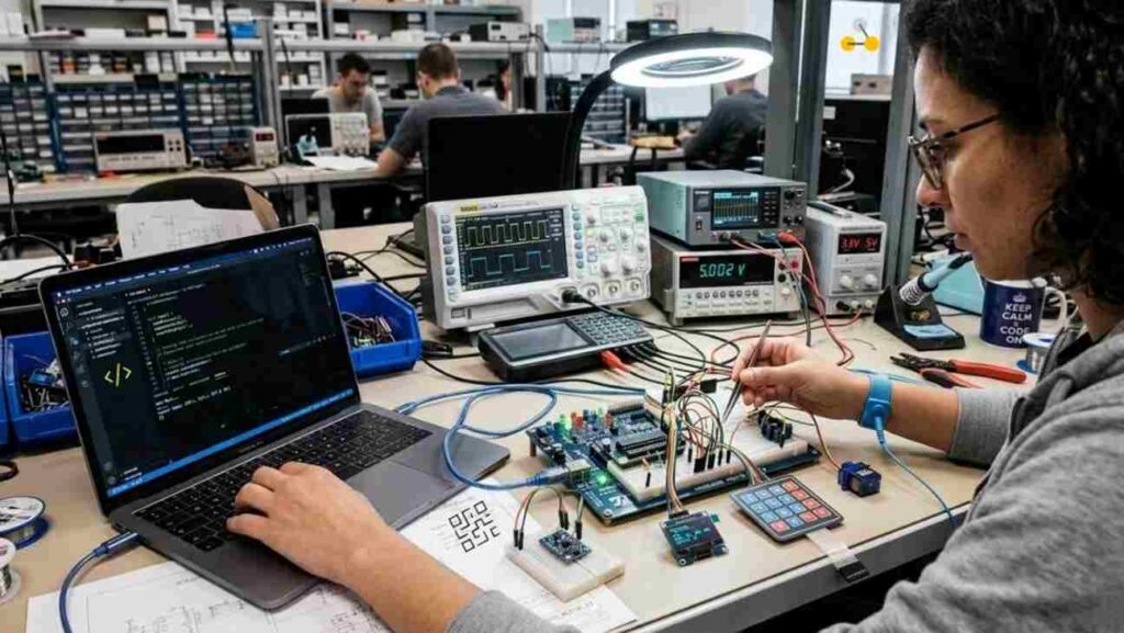
PROTOTYPE DEVELOPMENT PROCESS STEP BY STEP
01
REQUIREMENTS & SPECIFICATION
Define what your device must do. Inputs (sensors, buttons), outputs (LEDs, motors, displays), power constraints, environment (temperature, vibration), communication needs. Write a Feature List + Block Diagram.
02
MCU SELECTION
Match peripheral count (ADC, PWM, UART channels), flash/RAM size to your firmware estimate, power consumption, package type (DIP for breadboard, SMD for PCB), and cost. Use vendor comparison tools.
03
SCHEMATIC DESIGN
Draw full circuit: decoupling capacitors (100nF on every VCC pin), reset circuit, crystal oscillator (if external), programming interface (ICSP/SWD/UART bootloader), all peripheral connections.
04
BREADBOARD PROTOTYPE
Build the circuit on a solderless breadboard. Use a dev board (Arduino/Nucleo) to validate logic before finalizing hardware. Keep wires short. Validate power rails with multimeter.
05
FIRMWARE DEVELOPMENT
Write modular code — HAL abstraction, peripheral drivers, application logic separated. Use version control (Git). Write for testability. Flash and test iteratively.
06
PCB LAYOUT
Translate schematic to PCB. Follow design rules (trace widths, clearances). Place decoupling caps close to IC pins. Pour ground plane. Run DRC. Generate Gerber files.
07
PCB FABRICATION & ASSEMBLY
Order PCB from fab (JLCPCB, PCBWay, OSHPark). Solder components (SMD reflow or hand solder). Inspect under microscope or magnifier for cold joints, shorts, tombstoning.
08
BRING-UP & VALIDATION
Power on with current-limited supply. Measure voltages, clock signals. Flash firmware. Verify all peripherals. Run boundary scan and built-in self-test (BIST).
09
TESTING & CERTIFICATION
Functional test, stress test (temperature, voltage extremes), EMC pre-compliance, ESD testing. For products: FCC/CE/RoHS if required.
10
PRODUCTION ITERATION
BOM optimization, Design For Manufacture (DFM), test fixture design, programming jig for volume production, OTA firmware update mechanism.
BILL OF MATERIALS(BOM) IN DETAILS
| COMPONENT | VALUE | PURPOSE | PACKAGE |
|---|---|---|---|
| MCU | ATmega328P / STM32F103 | Main controller | DIP-28 / LQFP-48 |
| Crystal | 16MHz / 8MHz | Accurate clock source | HC-49S |
| Cap (load) | 22pF × 2 | Crystal load caps | 0402 |
| Cap (decouple) | 100nF × N | VCC decoupling (per IC pin) | 0402 |
| Cap (bulk) | 10–100μF | Power supply stabilization | 1206 / Electrolytic |
| Resistor | 10kΩ | RESET pull-up | 0402 |
| LED | Any color | Status indicator | 0402 / 3mm THT |
| Resistor | 220–470Ω | LED current limiting | 0402 |
| LDO Regulator | AMS1117-3.3 / MIC5205 | 3.3V regulation | SOT-223 |
| ICSP Header | 2×3 pin 2.54mm | Programming interface | THT |
PROGRAMMING LANGUAGES
C / C++
Industry standard for embedded. Direct hardware access. Deterministic memory (no GC). Used in Arduino (C++), AVR-GCC, STM32 HAL, FreeRTOS. Compiles to tight machine code.
MicroPython
Python subset running on MCU. Rapid prototyping. Interpreter overhead (~10× slower). Used on ESP32, RP2040, STM32. REPL over UART/USB for live testing.
Rust (Embedded)
Memory-safe systems language. Zero-cost abstractions. Growing embedded ecosystem (embassy, rtic). Ideal for safety-critical firmware without runtime overhead.
ARDUINO — BLINK (HELLO WORLD)
C++
// ─── Arduino Blink Example ─────────────────────────
// Toggles LED on pin 13 every 500ms
const int LED_PIN = 13; // Built-in LED on most boards
void setup() {
pinMode(LED_PIN, OUTPUT); // Configure pin as output
Serial.begin(9600); // Start UART at 9600 baud
Serial.println(“System Ready!”);
}
void loop() {
digitalWrite(LED_PIN, HIGH); // LED ON
delay(500);
digitalWrite(LED_PIN, LOW); // LED OFF
delay(500);
}
INTERRUPT-DRIVEN GPIO (ADVANCED)
C++
// ─── Button with hardware interrupt ─────────────────
volatile bool buttonPressed = false;
volatile uint32_t lastDebounce = 0;
void IRAM_ATTR buttonISR() { // ISR – runs in interrupt context
uint32_t now = millis();
if (now – lastDebounce > 50) { // 50ms debounce
buttonPressed = true;
lastDebounce = now;
}
}
void setup() {
pinMode(2, INPUT_PULLUP);
// Trigger ISR on falling edge (button press pulls LOW)
attachInterrupt(digitalPinToInterrupt(2),
buttonISR, FALLING);
}
void loop() {
if (buttonPressed) { // Check flag in main loop
buttonPressed = false; // Clear flag atomically
Serial.println(“Button pressed!”);
// Do work here…
}
}
ADC + PWM (SENSOR TO ACTUATOR)
C++
// ─── Read potentiometer → control LED brightness ─────
const int POT_PIN = A0; // Analog input (0–5V → 0–1023)
const int PWM_PIN = 9; // PWM-capable pin (~490Hz)
void setup() {
Serial.begin(115200);
pinMode(PWM_PIN, OUTPUT);
}
void loop() {
int raw = analogRead(POT_PIN); // 10-bit: 0–1023
int brightness = map(raw, 0, 1023,
0, 255); // Scale to 8-bit PWM
analogWrite(PWM_PIN, brightness); // Set duty cycle
// Formula: duty% = (brightness/255) × 100
Serial.print(“ADC:”); Serial.print(raw);
Serial.print(” PWM:”); Serial.println(brightness);
delay(20); // ~50Hz update rate
}
ESP32 Wi-Fi HTTP REQUEST
C++/ESP32
// ─── ESP32: Connect to Wi-Fi + GET request ───────────
#include <WiFi.h>
#include <HTTPClient.h>
const char* SSID = “YourNetwork”;
const char* PASSWORD = “YourPassword”;
const char* API_URL = “http://api.example.com/data”;
void setup() {
Serial.begin(115200);
WiFi.begin(SSID, PASSWORD);
while (WiFi.status() != WL_CONNECTED) {
delay(500); Serial.print(“.”);
}
Serial.println(“\nConnected: “ + WiFi.localIP().toString());
}
void loop() {
if (WiFi.status() == WL_CONNECTED) {
HTTPClient http;
http.begin(API_URL);
int code = http.GET();
if (code == 200) {
Serial.println(http.getString());
}
http.end();
}
delay(5000); // Poll every 5s
}
MICROPYTHON — QUICK REFERENCE
MicroPython
# ─── MicroPython on RP2040/ESP32 ─────────────────────
from machine import Pin, ADC, PWM, I2C
import time, uos
# GPIO
led = Pin(25, Pin.OUT) # RP2040 onboard LED
btn = Pin(14, Pin.IN, Pin.PULL_UP)
# ADC (12-bit: 0–4095 on ESP32)
adc = ADC(Pin(34))
adc.atten(ADC.ATTN_11DB) # 0–3.3V range
raw = adc.read()
# PWM (1kHz, 50% duty)
pwm = PWM(Pin(4), freq=1000, duty=512)
# I2C Scanner
i2c = I2C(0, scl=Pin(22), sda=Pin(21), freq=400000)
devs = i2c.scan()
print(f”I2C devices: {[hex(d) for d in devs]}”)
# Interrupt (IRQ)
def btn_cb(pin): print(“Pressed!”)
btn.irq(trigger=Pin.IRQ_FALLING, handler=btn_cb)
# Main loop
while True:
led.toggle()
time.sleep_ms(500)
CODE QUALITY CHECKLIST
⚡ ISR BEST PRACTICES ▶
Keep ISRs as short as possible. Set a flag, clear it in main loop. Never use delay() or heavy computation. Declare shared variables as volatile. Use atomic reads for multi-byte values. Disable interrupts briefly when reading volatile data.
🛡 DEFENSIVE CODING ▶
Always check return values. Validate input ranges before use. Use watchdog timer in production. Avoid dynamic memory allocation (malloc/new) in embedded — use static buffers. Check stack usage with canary values or compiler analysis.
💾 MEMORY MANAGEMENT ▶
Use const for lookup tables (stored in flash, not RAM). Minimize global variables. Use bit fields for flags. Profile RAM with avr-size or arm-none-eabi-size. Stack overflow is the #1 cause of mysterious crashes in MCUs.
🔄 STATE MACHINES ▶
Model complex behavior as finite state machines (FSM). Avoids deeply nested if-else. Use enum for states, switch-case for transitions. Non-blocking design: check current state each loop iteration instead of blocking with delay().
COMMUNICATION PROTOCOLS
| PROTOCOL | WIRES | SPEED | TOPOLOGY | USE CASE |
|---|---|---|---|---|
| UART | 2 (TX,RX) | 300–5Mbps | Point-to-point | Debug console, GPS, BT modules |
| SPI | 4 (MOSI,MISO,SCK,CS) | 1–100Mbps | Master–Slave | SD card, TFT display, sensors |
| I²C | 2 (SDA,SCL) | 100k–3.4Mbps | Multi-master bus | RTC, OLED, IMU, EEPROM |
| CAN | 2 (CANH,CANL) | 1Mbps | Differential bus | Automotive, industrial |
| USB CDC | 2 (D+,D-) | 12–480Mbps | Host–device | PC connectivity, DFU flashing |
| 1-Wire | 1 (DQ) | 16kbps | Multi-drop | DS18B20 temp sensors |
| MQTT/TCP | Wi-Fi | Mbps | Broker model | IoT cloud, ESP32 |
I²C IN DEPTH
C++
// ─── I²C — Read BMP280 temperature ────
#include <Wire.h>
#define BMP280_ADDR 0x76
#define REG_TEMP_MSB 0xFA
int32_t readRaw() {
Wire.beginTransmission(BMP280_ADDR);
Wire.write(REG_TEMP_MSB);
Wire.endTransmission(false); // Restart
Wire.requestFrom(BMP280_ADDR, 3);
int32_t raw = (Wire.read() << 12) |
(Wire.read() << 4) |
(Wire.read() >> 4);
return raw;
}
I²C Rules:
• Pull-up resistors on SDA and SCL (typically 4.7kΩ to VCC)
• Max bus capacitance: 400pF
• Each device has a unique 7-bit address
• Master generates clock; slave can stretch
• Max 127 devices per bus
• Use Wire.setClock(400000) for fast mode
• Pull-up resistors on SDA and SCL (typically 4.7kΩ to VCC)
• Max bus capacitance: 400pF
• Each device has a unique 7-bit address
• Master generates clock; slave can stretch
• Max 127 devices per bus
• Use Wire.setClock(400000) for fast mode
Address Conflicts: Use an I²C multiplexer (TCA9548A) when you have multiple devices with the same address. Scan with Wire.scan() to list all detected devices.
SPI TRANSACTION
C++
// ─── SPI — Full-duplex 16-bit transfer ────────────────────
#include <SPI.h>
#define CS_PIN 10
void setup() {
SPI.begin();
SPI.beginTransaction(SPISettings(
8000000, // 8MHz clock
MSBFIRST, // Bit order: MSB first
SPI_MODE0 // CPOL=0, CPHA=0
));
pinMode(CS_PIN, OUTPUT);
digitalWrite(CS_PIN, HIGH); // CS idle HIGH
}
uint16_t spiTransfer16(uint16_t data) {
digitalWrite(CS_PIN, LOW); // Assert CS
uint8_t hi = SPI.transfer(data >> 8);
uint8_t lo = SPI.transfer(data & 0xFF);
digitalWrite(CS_PIN, HIGH); // Deassert CS
return (hi << 8) | lo;
}
WIRELESS PROTOCOLS
Wi-Fi 2.4/5GHz
TCP/IP stack. HTTP/MQTT. High power (~200mA TX). ESP32/ESP8266. OTA updates possible.
Bluetooth LE
GATT profiles. Ultra-low power. Short range (~10m). nRF52, ESP32. Phone connectivity.
LoRa/LoRaWAN
Long range (2–15km). Very low power. Low data rate. Ideal for remote sensors, agriculture.
Zigbee/Thread
Mesh networking. Self-healing. Matter protocol support. Smart home automation.
DEVELOPMENT ENVIRONMENTS
ARDUINO IDE 2.x
Best for beginners. Supports hundreds of boards. Integrated library manager, serial plotter. C++ with simplified setup()/loop() structure.
VS CODE + PlatformIO
Professional IDE. Multi-board, multi-framework. Built-in debugger, static analysis (cppcheck), unit testing. Git integration. Best for large projects.
STM32CubeIDE
Official ST IDE. CubeMX code generator for HAL/LL. Integrated GDB debugger via ST-Link. Power consumption analysis. RTOS thread-aware debugging.
Keil µVision / IAR EWARM
Industry-leading commercial IDEs. Best code optimization, MISRA-C compliance. Used in automotive, medical, aerospace. Expensive but gold-standard.
Thonny IDE
MicroPython-focused IDE. REPL console. File manager for MCU filesystem. Step debugger. Best for RP2040 and ESP32 with MicroPython.
Wokwi Simulator
Browser-based MCU simulator. Run Arduino/ESP32 code without hardware. Supports sensors, displays, logic analyzer. Great for learning.
HARDWARE TOOLS
MULTIMETER
Measure DC/AC voltage, current, resistance, continuity, diode test. Essential for power rail verification and short-circuit finding. Get a 4000-count min.
OSCILLOSCOPE
Visualize digital/analog signals in time domain. Debug UART framing, SPI timing, PWM duty cycle. Minimum: 2ch, 50MHz bandwidth, 500MSa/s.
LOGIC ANALYZER
Multi-channel digital protocol decoder. UART, SPI, I²C, CAN decode. Saleae Logic / cheap 8ch clone. Works with PulseView (open-source).
PROGRAMMERS
AVR: USBtinyISP, AVRISP mkII. ARM: ST-Link V2, J-Link, CMSIS-DAP. Provide JTAG/SWD interface for flashing and live debugging.
BENCH POWER SUPPLY
Variable voltage + current limit. Protect circuits during bring-up. Current limiting prevents fire from shorts. 0–30V / 0–5A range typical.
HOT AIR + SOLDERING
Temperature-controlled iron (350°C for lead-free). Hot air station for SMD QFP/BGA rework. Flux, solder wick, IPA cleaning essential.
COMPILER & BUILD TOOLCHAIN
SHELL
# ─── AVR-GCC manual compile + flash ─────────────────
# Compile
avr-gcc -mmcu=atmega328p -DF_CPU=16000000UL \
-Os -std=c++11 -o main.elf main.cpp
# Size analysis
avr-size –format=avr –mcu=atmega328p main.elf
# Device: atmega328p
# Program: 1234 bytes (3.8% Full)
# Data: 256 bytes (12.5% Full)
# Generate hex
avr-objcopy -O ihex -R .eeprom main.elf main.hex
# Flash via avrdude (USBtinyISP)
avrdude -c usbtiny -p atmega328p \
-U flash:w:main.hex:i -v
# ARM (STM32) via OpenOCD
openocd -f interface/stlink.cfg \
-f target/stm32f1x.cfg \
-c “program firmware.elf verify reset exit”
PCB DESIGN SOFTWARE
KiCad 7+
Open-source. Professional quality. Schematic + PCB + 3D view. SPICE simulation. Large community. Industry adoption growing rapidly. FREE
EasyEDA / LCEDA
Browser-based. Integrated JLCPCB ordering. Huge component library. LCSC part links. Best for quick affordable PCBs. FREE
Altium Designer
Industry gold standard. Multi-board, constraint-driven. High-speed design, SI/PI analysis. Used at major OEMs. PAID
PCB LAYER STACK
PCB CROSS-SECTION VIEW
TOP COPPER (Cu) — Signal routing, components
PREPREG (FR4) — Insulator 0.2mm
INNER Cu 1 — Ground Plane (solid pour)
CORE (FR4) — Main substrate 1.0mm
INNER Cu 2 — Power Plane (+3.3V, +5V)
PREPREG (FR4) — Insulator 0.2mm
BOTTOM COPPER (Cu) — Signal routing
SOLDER MASK — Green soldermask
SILKSCREEN — Component labels (white)
4-layer PCB | 1.6mm total thickness | 1oz copper
ACTIVE LAYERS:
◆ COPPER
◆ SILKSCREEN
◆ SOLDERMASK
◆ DRILL
DESIGN RULES & CONSTRAINTS
| PARAMETER | STANDARD | ADVANCED | NOTES |
|---|---|---|---|
| Min Trace Width | 0.15mm (6mil) | 0.1mm (4mil) | Signal traces. Power needs wider. |
| Power Trace Width | 0.5mm/A | IPC-2221 chart | 1A → 0.5mm min |
| Min Clearance | 0.15mm | 0.1mm | Between copper features |
| Via Drill | 0.3mm | 0.2mm (laser) | Finished hole; aspect ratio <10:1 |
| Via Annular Ring | 0.15mm | 0.1mm | Copper ring around drill |
| Soldermask Expansion | 0.05mm | 0.025mm | Per-side expansion from pad |
| Decoupling Cap Distance | <2mm | <0.5mm | Place caps directly under IC |
| Crystal keepout | 1mm | 2mm | No traces under crystal |
PCB LAYOUT CHECKLIST
⚡ POWER DISTRIBUTION ▶
Place bulk capacitor near power entry. 100nF decoupling cap within 0.5mm of each VCC/GND pin pair. Pour solid ground plane on inner layer. Star topology for analog ground. Separate analog and digital ground (join at one star point).
📡 HIGH-SPEED SIGNALS ▶
Route differential pairs together (USB, CAN, LVDS). Match trace lengths for clock signals. Avoid right-angle bends (use 45° or curved). Keep signal return paths unbroken. Add series termination resistors (22–100Ω) on fast edges.
🔌 CRYSTAL OSCILLATOR ▶
Place crystal as close to MCU as possible. Keep traces short and symmetric. Ground guard ring around crystal and load caps. No signal traces under crystal. Shield from airflow if possible.
🛡 EMC / EMI REDUCTION ▶
Solid ground plane reduces emissions significantly. Route high-frequency signals over ground plane. Add ferrite beads on power inputs. Keep switching regulator components tightly grouped. Add TVS diodes on I/O connectors for ESD protection.
🏭 DFM GUIDELINES ▶
Minimum component spacing: 0.15mm. Fiducial marks for automated assembly (3 minimum, 1mm copper + 3mm keepout). Tooling holes in corners. Orient all polarized components the same direction. Avoid components on board edge (5mm keepout).
📋 GERBER OUTPUTS ▶
Export: GTL (top copper), GBL (bottom copper), GTS (top soldermask), GBS (bottom soldermask), GTO (top silkscreen), GKO (board outline), DRL (drill file). ZIP and upload to fab. Always review in Gerber viewer before ordering.
PCB Fabrication Services: JLCPCB and PCBWay offer 5–10 PCBs for $2–5 (2-layer, 100×100mm). Standard lead time: 3–7 days. Add PCBA (assembly) for SMD components from their LCSC parts library. Use ENIG (gold) finish for fine-pitch components.
TESTING METHODOLOGY
UNIT TESTING
Test individual functions in isolation. Use Unity or Ceedling frameworks. Mock hardware abstraction layer (HAL). Run tests on host PC, not MCU, for speed.
INTEGRATION TESTING
Test module interactions (driver + middleware + application). Verify communication between MCU and peripherals. Use hardware-in-the-loop (HIL) testbench.
STRESS TESTING
Soak test at operating temperature extremes (-20°C to +85°C for commercial). Voltage variation (±10% supply). Long-duration burn-in (24–72 hours continuous).
DEBUGGING TECHNIQUES
🔴
PRINTF / SERIAL DEBUG
Simplest method. Print values over UART. Low overhead but adds latency and may alter timing. Use Serial.print() in Arduino, printf() via semihosting in ARM. Remove before production.
🟡
GPIO TOGGLE TIMING
Toggle a GPIO pin at specific code points, measure with oscilloscope. Zero overhead method for timing analysis. Measure ISR latency, loop timing, task scheduling.
🟢
JTAG/SWD LIVE DEBUGGER
Full breakpoint debugging: set breakpoints, step through code, inspect registers and memory live. Requires J-Link or ST-Link probe. Use in GDB or IDE debugger. Best method for complex bugs.
🔵
RTOS TRACE (SEGGER SystemView)
Real-time task scheduler visualization. See task switches, ISR timing, CPU utilization, blocking times. Essential for FreeRTOS debugging and optimization.
POWER CONSUMPTION MEASUREMENT
C++
// ─── ESP32: Deep sleep + wake on timer ───────────────
#include <esp_sleep.h>
#define SLEEP_DURATION_US 30000000 // 30 seconds
void setup() {
Serial.begin(115200);
Serial.println(“Awake! Doing work…”);
// Read sensor, transmit data
doWork();
// Configure deep sleep (10μA total)
esp_sleep_enable_timer_wakeup(SLEEP_DURATION_US);
Serial.println(“Going to sleep…”);
Serial.flush();
esp_deep_sleep_start(); // Never returns
}
// Power profile:
// Active (Wi-Fi TX): ~240mA
// Active (no radio): ~30mA
// Light sleep: ~0.8mA
// Deep sleep: ~10μA
// Battery life = capacity_mAh / avg_mA
SIGNAL QUALITY MEASUREMENTS
| MEASUREMENT | TOOL | WHAT TO CHECK | PASS CRITERIA |
|---|---|---|---|
| Supply Noise | Oscilloscope (AC coupling) | VCC ripple under load | <100mV p-p |
| Clock Jitter | Oscilloscope (persist mode) | Edge timing variation | <100ps for USB |
| UART Framing | Logic Analyzer | Start/stop bits, parity | No framing errors |
| I²C ACK | Logic Analyzer | Slave acknowledges each byte | ACK after every byte |
| ADC Noise | Serial plotter (idle input) | Code variation with stable input | ±1–2 LSB noise floor |
| Current Draw | Multimeter / Current probe | Active and sleep currents | Per datasheet spec |
COMMON PROBLEMS & SOLUTIONS
🔴 MCU NOT RESPONDING / WON’T PROGRAM
Check: Power supply voltage (measure VCC pin, confirm 3.3V or 5V ±5%). Verify GND connection. Reset circuit: RESET pin should be pulled HIGH (10kΩ to VCC).
Programmer connection: Check ICSP/SWD wires, try slower speed.
Fuse bits: AVR fuse settings may have disabled clock or ISP. Use high-voltage programmer to recover.
Brown-out: Supply voltage dipping below BOD threshold during programming.
🔴 RANDOM RESETS / UNEXPECTED BEHAVIOR
Check power supply: Scope VCC for noise/dips under load. Add bulk capacitance.
Stack overflow: Use avr-size or compiler stack analysis. Increase stack size or reduce recursion.
Watchdog timer: Verify wdt_reset() is called regularly.
Interrupt re-entrancy: Global interrupts enabled inside ISR?
Floating inputs: Enable internal pull-ups on unused input pins.
🔴 I²C NOT WORKING / NO ACK
Pull-up resistors missing: Add 4.7kΩ from SDA and SCL to VCC. Without pull-ups, lines float high but can’t be driven properly.
Wrong address: Run I²C scanner to find actual device address. Check address pins (A0/A1/A2 on many ICs).
Bus stuck: Clock the SCL line 9 times manually to release stuck slave.
Voltage mismatch: 5V MCU driving 3.3V device — use level shifter.
🔴 ADC READINGS NOISY / INACCURATE
Power noise: Add 100nF + 10μF between AVCC and GND. Add 10μH inductor between VCC and AVCC.
Source impedance: ADC needs low source impedance (<10kΩ). Add opamp buffer for high-impedance sensors.
Sampling too fast: Add acquisition delay, enable auto-trigger mode.
Averaging: Take 8–64 samples and average for lower noise floor.
🔴 UART GARBAGE DATA / FRAMING ERRORS
Baud rate mismatch: Both sides must match exactly. With 16MHz crystal, error at 115200 = 0.16% (acceptable). With internal RC oscillator: up to 3% error — too much for 115200.
TX/RX crossed?: TX of transmitter → RX of receiver.
Voltage levels: RS-232 is ±12V, UART is 0–3.3/5V — need MAX232 converter.
Stop bits: Check 1 vs 2 stop bit setting.
🔴 PCB SHORT CIRCUIT / SMOKE
Prevention: Use current-limited bench supply during first power-on. Start at 100mA limit.
Diagnosis: Use thermal camera or frozen spray to find hot components. Measure resistance between VCC and GND (should be >100Ω).
Common causes: Solder bridge between adjacent pads, missing solder mask between fine-pitch pads, incorrect capacitor polarity (electrolytic).
Fix: Inspect under 10× magnification, use solder wick to remove bridges.
🔴 FIRMWARE HANGS / INFINITE LOOP
Enable watchdog: If firmware hangs, WDT will reset after timeout.
SWD breakpoint: Attach debugger, pause execution, inspect PC register to see where it’s stuck.
Loop analysis: Add LED heartbeat toggle in main loop — if LED stops, CPU is stuck.
Division by zero: Check all divisions — if divisor can be 0, it causes undefined behavior on ARM (HardFault).
🔴 ESP32 / WIFI CONNECTION ISSUES
Power supply: ESP32 draws 240mA during Wi-Fi TX peak. USB serial adapters often limited to 100–500mA — add external 5V supply. Add 100μF capacitor near ESP32 VCC.
Antenna: Keep antenna area free of copper pours. Don’t cover with metal enclosure.
Channel congestion: Try channels 1, 6, or 11.
Reconnect logic: Always implement WiFi.reconnect() with backoff in production.
DIAGNOSTIC DECISION TREE
Systematic Debug Process:
1. Is there power? → Measure VCC and GND pins with multimeter
2. Is there a clock? → Scope MCU clock pin for oscillation
3. Is firmware running? → Toggle LED in setup(), watch for activity
4. Is peripheral responding? → Check specific protocol with logic analyzer
5. Is data correct? → Print/log values, compare to expected
LEARNING ROADMAP
✓
STAGE 1 — FOUNDATIONS
Electronics basics: Ohm’s law, voltage dividers, capacitors, transistors. Binary/hex numbers. Installing Arduino IDE.
✓
STAGE 2 — FIRST PROJECTS
Blink LED. Read button. Potentiometer → ADC → Serial print. PWM servo control. 7-segment display.
→
STAGE 3 — COMMUNICATION
I²C sensors (BME280, MPU6050). SPI displays (ST7789, ILI9341). UART to PC. Libraries and drivers.
4
STAGE 4 — INTERRUPTS & TIMERS
Hardware interrupts. Timer ISRs. PWM generation. Input capture. Non-blocking code architecture.
5
STAGE 5 — IoT & WIRELESS
ESP32 Wi-Fi, MQTT, REST APIs. BLE GATT services. OTA firmware updates. Cloud connectivity (AWS IoT, Thingspeak).
6
STAGE 6 — CUSTOM PCB
KiCad schematic entry. PCB layout fundamentals. Order first PCB from JLCPCB. Solder and bring up.
7
STAGE 7 — RTOS
FreeRTOS tasks, queues, semaphores, mutexes. Task priorities and scheduling. Deadlock prevention. Stack sizing.
8
STAGE 8 — STM32 / BARE METAL
Register-level programming. HAL vs LL drivers. Clock tree. DMA transfers. Low-power modes. JTAG debugging.
9
STAGE 9 — ADVANCED TOPICS
Bootloader development. Cryptography (AES, TLS). Secure firmware updates. CAN bus. Motor control (FOC). Signal processing (FFT, filters).
SKILL PROFICIENCY
RECOMMENDED RESOURCES
📚 BOOKS
Programming Embedded Systems (O’Reilly) • Making Embedded Systems by Elecia White • The Art of Electronics (Horowitz) • AVR Programming by Elliot Williams
🌐 ONLINE
Random Nerd Tutorials • Embedded.fm podcast • Phil’s Lab (YouTube) • DigiKey TechForum • StackExchange Electrical Engineering
🛠 PRACTICE
Hackaday.io projects • Instructables • GitHub embedded repos • Wokwi simulator • TinkerCAD circuits (beginner)
KNOWLEDGE CHECK
Test your understanding. Click an answer to check it.
Q1. What is the purpose of a decoupling capacitor (100nF) placed near an IC’s VCC pin?
Q2. Why should variables shared between an ISR and main loop be declared
volatile?Q3. On an I²C bus, what happens to the bus when no device is driving it?
Q4. A 10-bit ADC reads a 2.0V signal with a 5V reference. What is the raw digital value?
Q5. What is the main advantage of a solid ground plane layer in a PCB?
Q6. What is the difference between
delay(1000) and a non-blocking approach using millis()?