
Microwave Communication Architecture
Microwave technology serves as the “wireless fiber” of modern telecommunications, in the situations where laying fiber optic cables is expensive or impractical due to long distances (over 30 kilometers). This line-of-sight wireless technology uses high-frequency radio waves for point-to-point data transmission and provides a crucial transport layer for mobile networks in areas where Physical laying cables is difficult or costly.
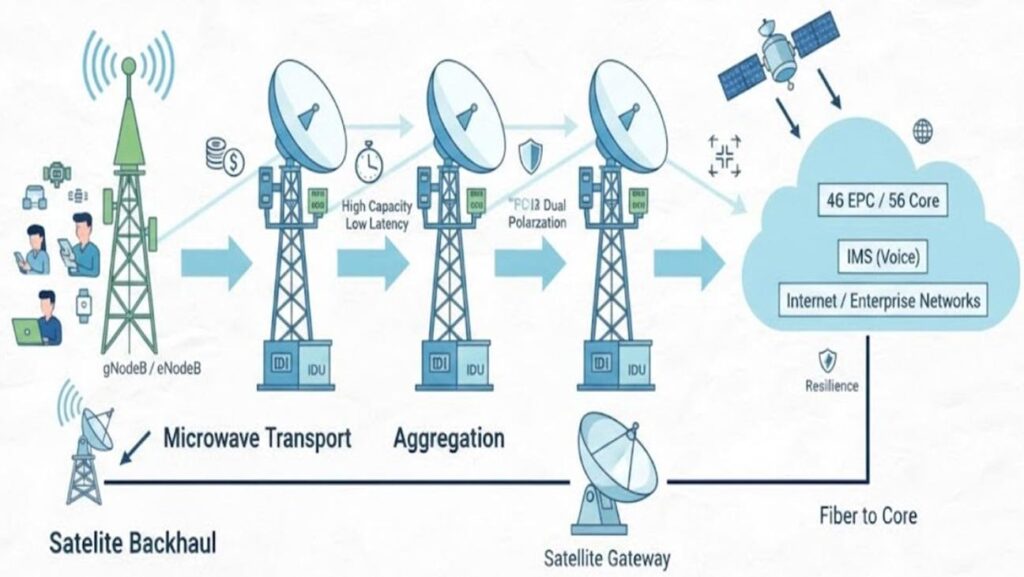
Network Infrastructure Visualization
1 The Access Node (RAN / Site)
- Elements: gNodeB (5G), eNodeB (4G), or BTS (2G/3G).
- Function: Generates user plane and control plane traffic (voice and data).
- Requirement: High-bandwidth, low-latency transport to reach the Mobile Core.
Key Concepts
Integration of Common Public Radio Interface (CPRI) and eCPRI for 5G fronthaul over microwave. Baseband Unit (BBU) functional splitting (Options 2, 7.2) dictates transport overhead.
Challenges & Issues
Strict jitter and wander requirements for 5G synchronization. High packet loss at the RAN interface can trigger RRC connection drops for mobile users.
2 Microwave Transport Components

Detailed Schematic: Microwave Backhaul Network Architecture
Physical Hardware Configuration
Split-Mount Architecture
The traditional approach dividing indoor and outdoor tasks.
- IDU: Rack-mounted switching/modulation.
- ODU: Tower-mounted RF conversion.
- Coaxial: Carries DC power and IF signals.
Advanced Deployments
- All-Outdoor: Zero footprint; full integration.
- All-Indoor: Used for high-power long-haul.
- XPIC: Dual polarization for 2x capacity.
- Space Diversity: Combats multi-path fading.
Considerations & Quality Factors
Waveguide Losses: In All-Indoor systems, the length of the waveguide significantly impacts signal strength. Antenna Wind Loading: Large parabolic dishes require reinforced towers to prevent misalignment during storms.
Component Reliability Issue
Thermal Management: In All-Outdoor units (AOU), passive cooling fins can become clogged with debris, leading to thermal throttling where the ODU reduces transmit power to protect circuitry. Design must include strict maintenance schedules for tropical or high-dust environments to ensure consistent SNR (Signal-to-Noise Ratio).
Traffic Flow Logic
3 Frequency Spectrum & Bandwidth
| Frequency Band | Typical Range | Characteristics |
|---|---|---|
| Sub-6 GHz | 50+ km | High penetration, low capacity. Used for rural. |
| 6 – 23 GHz | 10 – 40 km | Standard backhaul. Reliable in rain. |
| 26 – 42 GHz | 2 – 7 km | Higher capacity, sensitive to absorption. |
| E-Band (70/80 GHz) | 1 – 3 km | 10 Gbps+ capacity. The backbone of 5G. |
Interference Challenges
Frequency Overlap: In dense urban areas, Hi-Lo frequency planning is vital to prevent self-interference. Ducting: Atmospheric conditions can cause signals to travel much further than intended, causing co-channel interference.
Spectrum Considerations
Licensing costs vary significantly per MHz. Unlicensed V-Band (60GHz) is susceptible to oxygen absorption (60GHz peak), limiting its use to very short “whisper” links.
Atmospheric Attenuation
At frequencies above 10 GHz, Hydrometeor Attenuation (rain fade) becomes the dominant limiting factor. Raindrops absorb and scatter RF energy. Designers must use Crane or ITU-R P.530 rain models to predict availability. For E-Band, even heavy fog can degrade the link, necessitating a “Multi-band” failover strategy where traffic shifts to a more robust 15GHz or 18GHz link during peak storms.
4 Network Topology & Protection
Protection Schemes
- 1+0 Single ODU/link. Non-redundant.
- 1+1 HSB Hot Standby hardware redundancy.
- 1+1 SD Space Diversity against fading.
- N+0 Link aggregation for capacity.
Hierarchy
- Access: Last-mile connectivity from site to hub.
- Aggregation: Collecting traffic from multiple hub sites.
- Backhaul: Long-haul trunking to the core.
Topology Issues & Considerations
Chain Topology Risk: A single link failure at the start of a chain isolates all downstream sites. Ring Protection (ERP/G.8032): Offers < 50ms switching time but requires careful VLAN configuration to prevent loops. In 5G, Dual-Homing at the aggregation layer is preferred for maximum resilience.
5 Performance & Link Budget
Fade Margin: The safety buffer (in dB) between received signal level and receiver threshold.
Modulation: Systems use up to 4096QAM to maximize bits per Hz.
ATPC: Automatic Transmit Power Control reduces interference in clear weather.
Key Concepts in Link Budgeting
Free Space Path Loss (FSPL): L = 20 \log_{10}(d) + 20 \log_{10}(f) + 32.44
Calculates the basic attenuation based on distance (d) and frequency (f).
Reflections & Fresnel Zone: The first Fresnel zone must be at least 60% clear of obstacles (buildings, trees) to ensure Line-of-Sight (LoS) integrity.
QoS & Buffer Considerations
When Adaptive Coding and Modulation (ACM) kicks in, capacity can drop from 10 Gbps to 500 Mbps in seconds. Without Hierarchical Quality of Service (H-QoS), high-priority traffic (Voice/Signaling) will be dropped along with Best-Effort data. Engineers must configure Weighted Random Early Detection (WRED) and strict priority queuing to ensure the link remains “available” for critical services even during severe fading.
6 Modern Features & 5G Era
IP-Centric Intelligence
- • Full IP/MPLS & Segment Routing
- • ACM (Adaptive Coding & Modulation)
- • SDN-based traffic engineering
- • SyncE & IEEE 1588v2 Precision Timing
The 5G Advantage
In the 5G era, Multi-band technology bonds a high-availability low-frequency link (e.g. 18 GHz) with a high-capacity E-Band link to provide high-capacity, low-latency backhaul globally.
Ongoing Considerations & Issues
Transitioning to IPv6 in the management plane. Cybersecurity: Modern MW links are vulnerable to sniffing if L1/L2 encryption is not enabled. Software Defined Networking (SDN): Moving towards centralized control for dynamic traffic re-routing during atmospheric fade events.
The Future: AI-Driven Microwave
Emerging architectures are incorporating AI-based Predictive Maintenance. By analyzing historical SNR data and local weather feeds, the IDU can anticipate a fade event before it happens, proactively rerouting low-priority traffic via an alternative path. This reduces the “hit” time for 5G network slices and ensures that uRLLC (Ultra-Reliable Low Latency Communication) requirements are met even in challenging geographical terrains.