

Submarine Cables:
The Abyssal Foundation
Facilitating over 99% of global data exchange, subsea fiber optic networks represent the absolute zenith of contemporary industrial engineering and maritime precision. This comprehensive compendium delineates the intricate operational lifecycle governing their global deployment and structural longevity.
Manufacturing Lifecycle
Industrial Synthesis & Advanced Material Science
01 Conductor Stranding Protocols
The fabrication sequence commences with ultra-high-purity copper filaments helically wound to constitute the primary conductive architecture. This core must sustain continuous high-voltage DC transmission (up to 15kV) with nominal resistive attenuation across transoceanic spans exceeding 10,000km.
02 Fiber Insertion & Steel Tubing
Optical fibers (utilizing G.654.D ultra-low loss pure silica cores) are encapsulated within a pressure-tolerant stainless steel vessel. This containment tube undergoes continuous laser-welding to guarantee absolute hermetic integrity against abyssal pressures.
- Hermetic seal validation (Helium Leak Test)
- Zero-tension fiber oscillation control
- Hyperbaric stress testing (800 Bar)
- Ultrasonic weld structural integrity audit
Structural Cross-Section Analysis
Atmospheric Degassing
Crucial evacuation of volatile methane byproducts from polymerization to maintain long-term dielectric stability.
Extrusion Sheathing
Application of high-density polyethylene barriers to facilitate primary moisture exclusion and environmental isolation.
Helical Armouring
Deployment-optimized galvanized steel wrapping providing superior mechanical protection against benthic threats.
Bituminous Serving
Bitumen-infused polypropylene yarn coating engineered for optimized seabed abrasion resistance and friction management.
Network Architecture
Dry Plant vs Wet Plant Systemic Synchronization
Systemic Network Topology & Signal Progression
Onshore Infrastructure
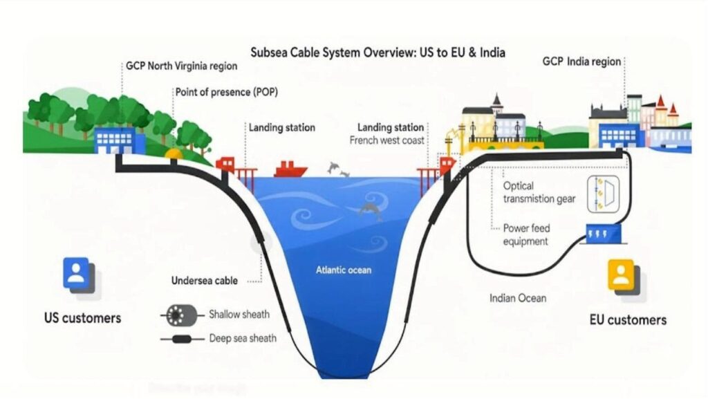
Landing Station (CLS)
The fortified facility where subsea links terminate. These high-availability stations house the SLTE (Submarine Line Terminal Equipment) which utilizes coherent optics to facilitate transoceanic transmission without passive regeneration requirements.
Power Feed Equipment (PFE)
High-reliability DC power conversion units providing a constant stabilized current (standardized at 1A) to submerged amplifiers. Critical features include:
Maritime Componentry
Repeaters (EDFA Units)
Optical Erbium-Doped Fiber Amplifiers enclosed in beryllium-copper or titanium pressure vessels engineered for 8,000m depths. They augment signal integrity at 60-100km periodic intervals.
Branching Units (BU)
Advanced subsea switching matrices that permit specific spectral wavelengths to be diverted to tertiary landing points via high-precision OADM (Optical Add-Drop Multiplexing).
Transoceanic Deployment
Operational Benchmarks & Commissioning Standards
| Phase | Operation | Technical Specifications & Methodology |
|---|---|---|
| Survey | Route Engineering | Multibeam bathymetric sonar mapping identifies “optimal risk” trajectories. This rigorous methodology bypasses coral biomes, shipwrecks, hydrothermal vents, and seismic faults to determine required “Armour Gradient” profiles. |
| Loading | Tank Spooling | Specialized cable vessels (e.g., 150m LOA) ingest thousands of tons into circular coiling tanks. This continuous operation lasts weeks, necessitating millimetric “slack optimization” during spooling procedures. |
| Lay | Surface Payout | Precision deposition on the abyssal plain. Dynamic tension is calculated in real-time based on vessel velocity, bathymetry, and sea state. Linear Cable Engines (LCE) ensure accurate contour following. |
| Burial | Jetting & Plowing | In shallow neritic zones (0-2000m), a 50-ton submersible “Sea Plow” is utilized to inter the cable 3m below the seabed. This mitigates risks from bottom-trawling, bio-interference, and anchors. |
| Landing | Shore Integration | Extraction through pre-commissioned HDD (Horizontal Directional Drilling) conduits into the CLS. This phase requires precise synchronization with tidal cycles and environmental regulatory windows. |
Maintenance
Service Continuity & Fault Mitigation Protocols
Rapid Response Repair Protocol
Following fault detection via high-resolution OTDR (Optical Time Domain Reflectometry), a specialized repair vessel is dispatched. To minimize latency costs, vessels are strategically pre-stationed at global maritime logistics hubs for accelerated mobilization.
Core Competencies
Specialized Technical Proficiencies & Certifications
OTDR Profiling
High-precision optical fault localization across transoceanic distances with meter-level accuracy.
HV Management
Supervising 15kV systems within high-salinity aquatic environments under strict safety mandates.
Molecular Splicing
Atomic-level silica fusion bonding with attenuation targets < 0.05dB per individual joint.
ROV Navigation
Coordinating complex subsea robotics within extreme hyperbaric zones for tactile repairs.
Industrial Best Practices
Systemic Operational Excellence & Risk Management
01. Slack Ratio Optimization
“Precision calculation of cable slack facilitates conformal mapping to seabed topography, preventing suspension (bridging). This is imperative in seismic zones with volatile elevation shifts to prevent mechanical fatigue.”
02. Temporal Synchronization
“Coastal landings must be synchronized with lunar tidal windows and biotic migration corridors to mitigate ecological footprints and optimize saturation diver operational visibility.”
03. Dynamic Power Calibration
“PFE current output must be dynamically modulated based on telemetry from subsea thermal sensors. Deep-sea temperature gradients significantly impact conductor resistance and EDFA gain efficiency profiles.”
Security & Future Horizons
Network Resilience & Technological Paradigm Shifts
Physical Infrastructure Safeguards
AIS (Automatic Identification System) geofencing of maritime vessels near sensitive cable corridors. Stationary or aberrant vessel behavior triggers automated alerts to mitigate anchor-related risks.
Smart-Cable Sensing Technology
Implementing DAS (Distributed Acoustic Sensing) to transform passive optical fibers into global seismometers. This enables sub-millisecond tsunami and earthquake detection for international warning agencies.
Autonomous Mesh Topology
Autonomous network redundancy facilitated by SD-WAN logic and “reconfigurable optical add-drop multiplexers” (ROADM) that perform millisecond-latency rerouting during unexpected fault events.