
IT Networking Fundamentals: Comparison of Active Network Devices
Detailed technical analysis of Hubs, Switches, and Routers. Understanding these core devices is essential for designing efficient, Config,Technical Concept, secure, and scalable infrastructures.
1. Quick Comparison Table
| Feature | Hub | Switch | Router |
|---|---|---|---|
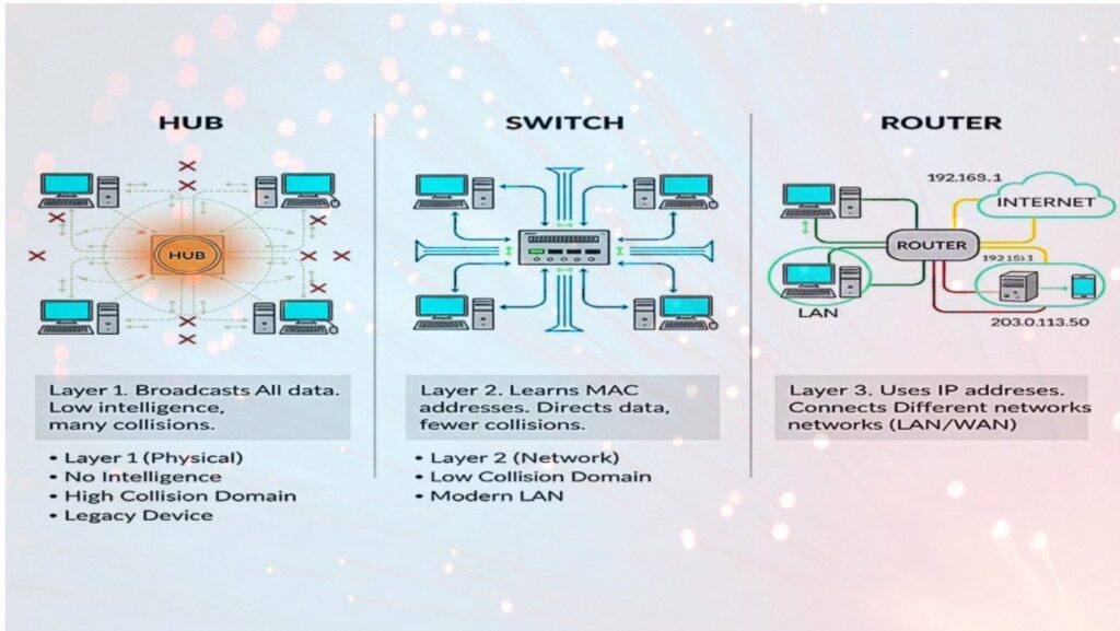
| OSI Layer | Layer 1 (Physical) | Layer 2 (Data Link) | Layer 3 (Network) |
| Intelligence | None (Passive) | Smart (Learns MACs) | Intelligent (Routing Logic) |
| Data Delivery | Broadcasts to all ports | Sends to specific MAC | Forwards based on IP |
| End-Device Focus | Broadcasts to PC/Printers | Direct Unicast to Computer | Subnet Gateway for LAN |
| Collision Domain | One shared domain | One per port | One per port |
| Broadcast Domain | One | One | Multiple (Blocks broadcasts) |
| Connectivity | Intra-network only | Intra-network only | Inter-network (LAN to WAN) |
Important: Network Health & Maintenance
Firmware Security Updates
Routers and Managed Switches must have their firmware updated regularly to patch vulnerabilities and improve routing table efficiency.
Environmental Monitoring
Hardware failure often results from overheating. Ensure racks have proper airflow for enterprise switches and routers handling high traffic.
Cabling Integrity
Layer 1 issues (faulty cables) can cause "CRC Errors" on switch ports, leading to packet loss that mimics software or configuration bugs.
Bandwidth Throttling
Monitors performance on switch ports connected to Printers or IoT devices to prevent them from saturating local bandwidth with broadcast noise.
Deployment: Where & Why?
Diagnostic Use
Used by network engineers to perform Packet Sniffing. Because a hub broadcasts everything to every port, an engineer can plug in a protocol analyzer to see all traffic on the segment without complex port-mirroring configs.
LAN Distribution
Used in Office Buildings and Data Centers. It is the core of internal communication. Essential for high-density environments where 24-48 devices need to talk to each other at high speeds (1Gbps/10Gbps) simultaneously.
Border Gateway
Used at the Network Edge. It is the "Post Office" of the internet. Used to bridge your private home/office LAN to the Internet Service Provider (ISP). Vital for security (Firewalls) and assigning IP addresses via DHCP.
Visual Architecture (Hardware View)
Router (Layer 3)
Low port density, high processing power for packet inspection.
Switch (Layer 2)
High port density (24/48 ports). Connects PCs and Servers directly.
Hub (Layer 1)
Basic signal repeater. Shared bandwidth across all ports. Half-duplex.
End Devices (Edge)
Endpoints that consume/produce data (PC, Printer, Laptop).
2. The Hub (Legacy)
A Hub is the simplest "dumb" device. It acts as a multi-port repeater.
Mechanism
When a packet arrives at one port, it is copied to all other ports regardless of destination.
Drawback
Creates massive traffic congestion and security risks (sniffing), as every device (PC/Printer) sees everyone else's traffic.
Modern Use: Rarely used today, except for specialized network monitoring or legacy labs.
3. The Switch (Modern Standard)
The backbone of a Local Area Network (LAN). A "smart" device that filters traffic.
Mechanism: The MAC Table
Maintains a 'Content Addressable Memory (CAM) table. When a frame arrives, the switch maps the source MAC (e.g., from a Computer) to the port and forwards frames only to the designated destination port (e.g., a Printer).
7. Spanning Tree Protocol (Loop Prevention)
Switches use *STP (IEEE 802.1D)* to prevent "Broadcast Storms" in redundant networks.
The Problem:
If there are two paths between switches, a broadcast frame will circle infinitely, crashing the network within seconds.
The Solution:
STP logically "blocks" redundant ports. If the primary link fails, STP unblocks the backup port automatically.
6. The ARP Process (Logic Bridge)
How does a Switch know where to send data? It uses the Address Resolution Protocol (ARP).
// Step-by-Step ARP Flow
- Host A wants to talk to Host B (knows IP, needs MAC).
- Host A sends an ARP Request (Broadcast: "Who has IP 192.168.1.5?").
- Switch broadcasts this to all ports.
- Host B (The Computer) recognizes its IP and sends an ARP Reply.
- Switch "learns" Host B's MAC and port association.
- Host A caches the MAC and begins direct communication.
4. The Router (Gateway)
Connects different networks (LAN to WAN). Functions as the intelligent gateway.
- 01 Routing Tables: Uses IP addresses and protocols (OSPF, BGP) to determine the most efficient paths across the global web.
- 02 Security: Performs NAT (Network Address Translation) and Firewalling to shield internal LANs (PC/Mobile/Printers).
- 03 Segmentation: Breaks up broadcast domains to prevent network-wide storms and increase performance.
8. Data Encapsulation & OSI Mapping
How data is "wrapped" as it travels down the OSI stack through hardware.
5. Technical Configurations (Cisco IOS)
Production-ready syntax for enterprise hardware provisioning.
Switch: Advanced VLAN & Port Security
running-config#L2! Layer 2 - Port Security Configuration
interface GigabitEthernet0/1
switchport mode access
switchport access vlan 10
switchport port-security
switchport port-security maximum 2
switchport port-security violation shutdown
spanning-tree portfast
! Inter-Switch Trunking (IEEE 802.1Q)
interface GigabitEthernet0/24
switchport mode trunk
switchport trunk allowed vlan 10,20,30Router: DHCP Server & NAT Config
! DHCP Pool for internal clients (PC/Computer/Printer)
ip dhcp pool INTERNAL_LAN
 network 192.168.10.0 255.255.255.0
 default-router 192.168.10.1
 dns-server 8.8.8.8

! Configure NAT Outside Interface (Gateway)
interface GigabitEthernet0/0
 ip address 203.0.113.1 255.255.255.252
 ip nat outside
 no shutdown

! Configure NAT Inside Interface
interface GigabitEthernet0/1
 ip address 192.168.10.1 255.255.255.0
 ip nat inside
Network Topology Visualizer
Detailed logical interconnection with packet flow animation including end devices.
Visual Key (Detailed Logic):
- Yellow Dashes: Bit-stream/Packet Flow activity between layers.
- Indigo Box: Routing, NAT, & Inter-network Gateway services.
- Blue Box: High-speed Frame Switching & Collision Domain isolation.
- Grey Lines: Physical Media (Copper/Fiber) carrying L1 electrical signals.
- Dark Rectangles: Endpoint nodes (consuming unique L2/L3 addresses).
Integrated System Architecture (Full Stack)
External Layer (WAN / Public)
This layer represents the untrusted public internet. The connection terminates at the Router's WAN port.
Input: Public IP (e.g., 203.0.113.1) via DHCP/PPPoE/StaticBoundary Control Layer (Router / Gateway)
Core Functions: Statefull Packet Inspection (SPI) Firewalling, DHCP Address Allocation, BGP/OSPF Routing, and VPN Termination.
Internal Distribution Layer (Switch)
Performance Logic: High-speed hardware-based frame forwarding (ASICs), Loop Management (STP/RSTP), and Power over Ethernet (PoE) for VoIP phones.
Access Layer (Endpoints)
The Switch Choice
Internal communication. If User A (PC) wants to send a document to the Office ,Printer, the traffic never reaches the router; the switch handles it instantly at wire-speed.
The Router Choice
External communication. If User A (Computer) wants to browse Google, the switch forwards the frame to the Default Gateway (Router) to be encapsulated and sent to the Internet.
Interview Prep: FAQ & Answers
Q1: Why is a Router needed if a Switch can connect devices?
A switch only connects devices within the same network (Layer 2). You need a Router to connect different networks (Layer 3), handle IP routing, and perform NAT so private devices can access the public internet.
Q2: What is the difference between a Collision Domain and a Broadcast Domain?
A Collision Domain is a segment where data packets can "collide" (Hubs have one, Switches have one per port). A Broadcast Domain is the segment where a broadcast frame is seen by all devices (Switches have one, Routers break them into many).
Q3: What happens when a Switch receives a frame with an unknown destination MAC address?
The switch will "flood" the frame out of all ports except the one it arrived on. This is called *Unicast Flooding*. Once the target device responds, the switch learns the MAC and updates its CAM table.
Q4: Why are Hubs considered "half-duplex"?
Because they can only send OR receive at one time. If two devices send simultaneously, a collision occurs. Switches are full-duplex, allowing simultaneous send/receive.
Practical Skills Checklist
Troubleshooting (L1-L3)
-
01
Cable Testing
Checking for "Straight-through" vs "Crossover" and verifying link lights on the switch.
-
02
The 'Ping' Test
Verifying L3 connectivity. Ping gateway (Router) first, then external DNS (8.8.8.8).
-
03
Traceroute
Identifying which router (hop) is dropping the packet in a multi-network path.
Configuration
-
04
VLAN Setup
Assigning ports to specific IDs to isolate HR from Guest traffic.
-
05
Static Routes
Manually telling the router how to reach a subnet not directly connected.
-
06
MAC Filtering
Restricting port access to specific device IDs (Printer/PC) at the switch level.